
7 mm Probe Installation Manual
System installation manual for the FloraPulse small probes and datalogger
720 Olive Dr Ste E
Davis CA, 95616
(530) 220-7668
This guide provides written instructions for installing the FloraPulse 7mm small probes and datalogger. We strongly recommend watching the installation video to see the whole process. Additional videos and manuals are linked for reference. All these and more are available at florapulse.com/resources.
Links to installation videos (check the FloraPulse YouTube channel for more videos)
- 7mm small probe installation for most crops (c-clamp)
- 7mm small probe installation (hammer)
- 7mm small probe installation into thick bark
- How to remove/reuse probes
- Quick start for the FloraPulse datalogger
- Introduction to FloraPulse online dashboard
Product manuals
- Analog probe
- SDI-12 probe
- Datalogger
- Datalogger use and features (detailed video)
How to use FloraPulse data for irrigation
- Understanding tree water potential
- Using tree water potential for irrigation
- Crop validation database – find your crop here for guidelines and tips
- Data analysis and troubleshooting guide
- Microtensiometers: a new tool to monitor your apple trees for deciding when and how much to irrigate
- Scheduling Irrigation with a Pressure Chamber Part 1, Part 2 (for grapes – use the same SWP thresholds)
- Soil Doctor: comparison of FloraPulse with soil moisture sensors and soil water potential sensors
Non-standard installations/procedures
Miscellaneous
- How to pick a FloraPulse sensor style
- Spreadsheet to process raw sensor data for datalogger SD card, SDI-12 or analog probes
- Programs to read probes with Campbell Scientific loggers
Crop requirements
- Minimum stem diameter of 0.65” (1.7 cm). Installation into smaller stems or vines may cause inaccurate readings because the sensor installation wound is too large and will not seal appropriately against the trunk/branch.
- Ensure wood is healthy. Installation into diseased or very old trees/vines may produce inaccurate results. Please ensure the sensor is installed into an area of active xylem.
- Install after leaf-out. We recommend only installing sensors after leaf-out. All FloraPulse testing has been with vines/trees once the leaves come out. Installation during the winter may or may not work well.
Sensor reuse and re-installation
- Sensor installations are semi-permanent and should only be moved when necessary. The sensors require 1-2 days post-installation to begin reading accurately, and each installation requires a new metal sleeve. The sensors are also fragile and more likely to break during removal/reinstallation.
- In many crops, the sensor installation wound closes slightly during the winter, decreasing measurement accuracy. For best results, we recommend installing a new sensor every season after leaf-out. You have two other alternatives: (1) you may remove and reinstall the sensor in a new wound at the beginning of the season. Or (2) you may wait to see how the sensor responds the second season for a few weeks – if the data looks reasonable you can skip the re-installation. We know that prunus requires re-installation, and that grapes seem to do alright without reinstallation. As always, more research is needed.
- Temperatures below 0 °C can freeze the water reservoir inside the sensor and damage it. This may cause problems in areas with cold winters. Sensors should only be installed after risk of serious frost has passed. If you intend to re-use the sensor for a second season, remove it before freezing temperatures happen, then reinstall it in the spring after leaf-out.
- We recommend that FloraPulse-instrumented trees/vines be hand-harvested. Machinery, shaking and vibrations can damage the sensor wires and datalogger, and will void all warranties.
Installation kit and tools needed
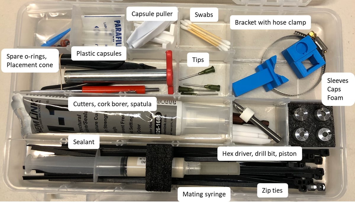
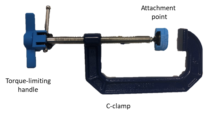
Materials for install
- Install tools:
- Cordless drill (not provided)
- Modified C-clamp
- Spatula
- Wire cutter
- Drill bit with depth stop
- Clamping guide
- Hose clamps
- 5/16” hex socket drill attachment
- Thick-bark toolbag (1-1/4” Forstner bit + centering guide) – ships automatically with thick-bark probe orders (part number mt_ana_7); needed when bark is thicker than ~1 cm, see Thick bark installation
- For every 2 probes:
- 2 sleeves and caps
- Mating compound syringe
- Luer lock syringe tips
- Insulation
- Zip ties
- Napkins
- M-1 sealant (for every 10+ probes)
Install instructions
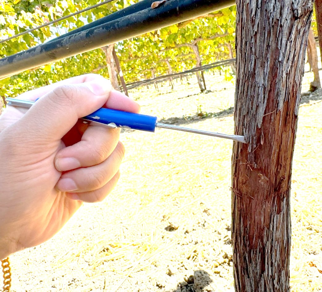 | 1. Install into small trunks, vines or branches of at least 0.65” diameter. Installation should be performed without long pauses to avoid drying out the wound, sensor, or mating compound. Pick a site that is healthy and flat without knots. In crops with a hard bark, such as grapevines, remove excess bark with the spatula, leaving a thin (~2 mm) layer of bark only. |
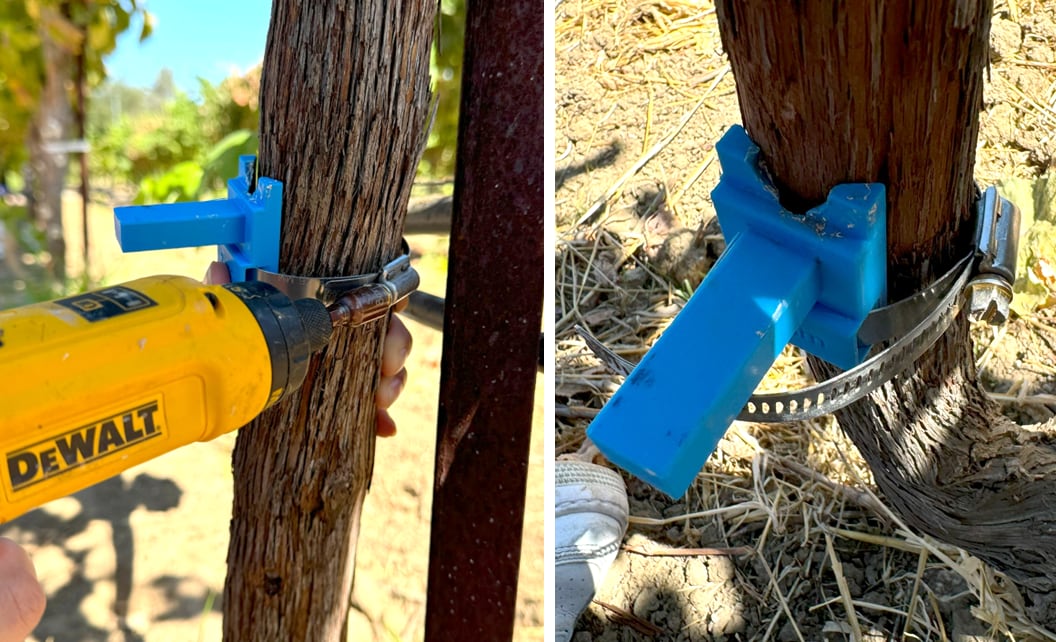 | 2. Fasten the bottom bracket at the desired installation site. Use the hex driver with a drill or electric screwdriver to tighten the hose clamp. Ensure the bracket is firmly attached and does not wiggle. Keep the screw head to the side of the bracket, not the back. In a later step, the c-clamp requires a clear back surface for pushing. |
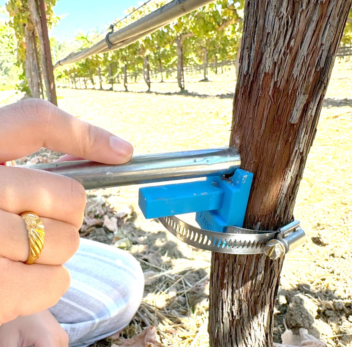 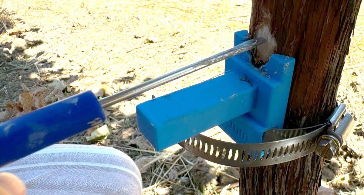 | 3. Place the cork borer in the U-shaped groove and push/rotate to cut through the bark and phloem. The phloem is usually much softer than the xylem, thus the borer will easily cut through the phloem, but struggle to cut into the xylem. The amount of force needed to cut through the phloem depends on the crop and growth stage. Use the spatula to pull out the plug of phloem. Use the spatula to scrape the exposed xylem surface. This will remove any remaining phloem and ensure a clean surface for the sealant. |
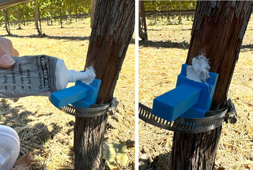 | 4. Apply sealant to the exposed xylem. Use the application tip to spread the sealant around the xylem and to ensure it sticks to the surface and there are no voids. It is ok to get sealant on the plastic bracket – we will clean it later. |
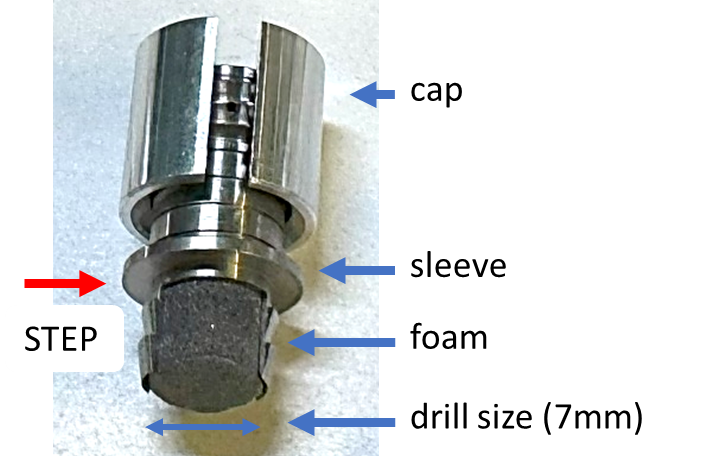 | Diagram of the installation parts. The sleeve gets pushed into the xylem wood. The foam cylinder sits inside the sleeve, and the metal cap is threaded onto the sleeve. |
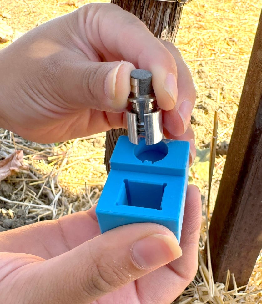 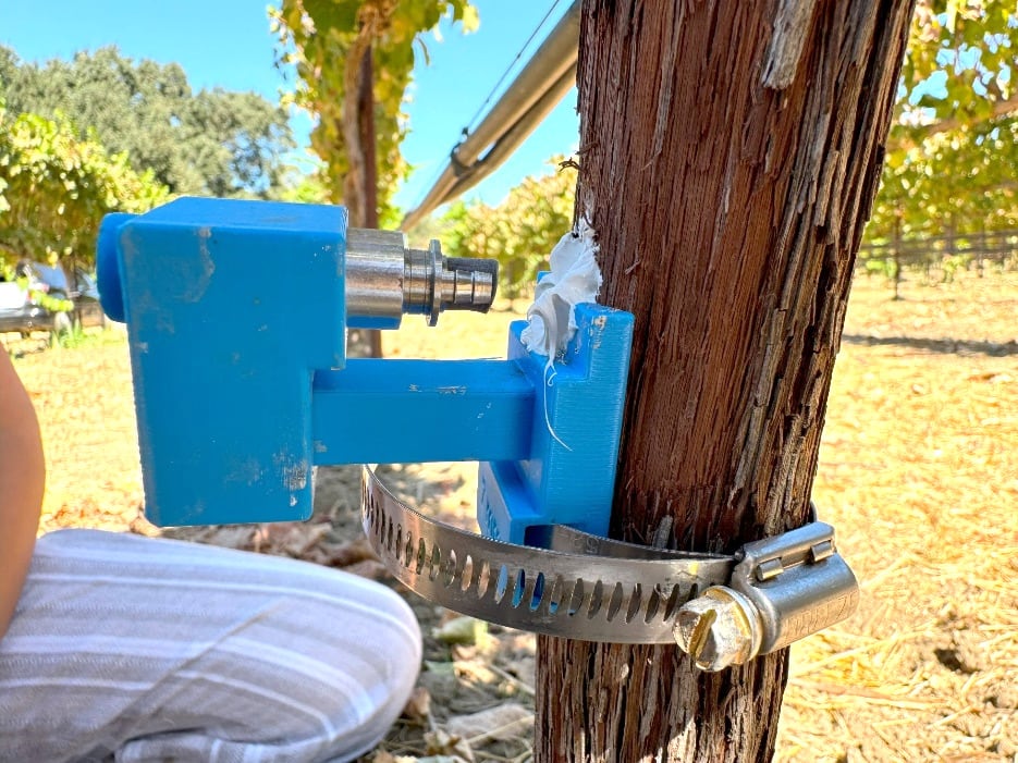 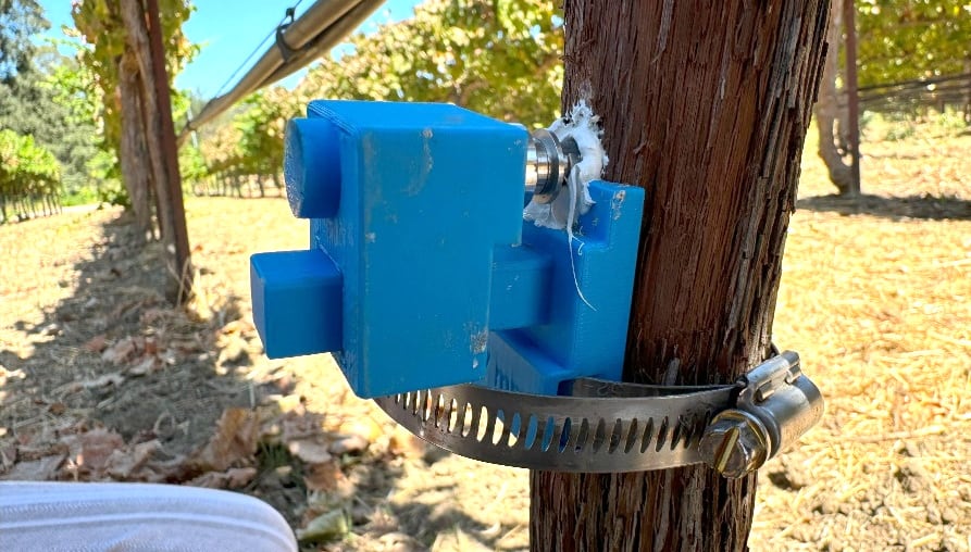 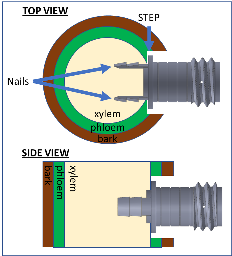 | 5. Insert the cap into the end of the top bracket. There is a notch in the bracket that aligns with the cap. Slide the top bracket onto the bottom bracket so that the sleeve nails face the trunk. Rotate the sleeve so that the nails are parallel with the trunk/branch and on the sides of the hole. Push the top bracket with the sleeve+cap into the bark slightly, and confirm the correct orientation of the barbs as shown in the top-view and side-view diagram. |
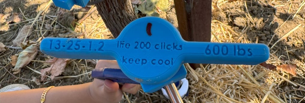 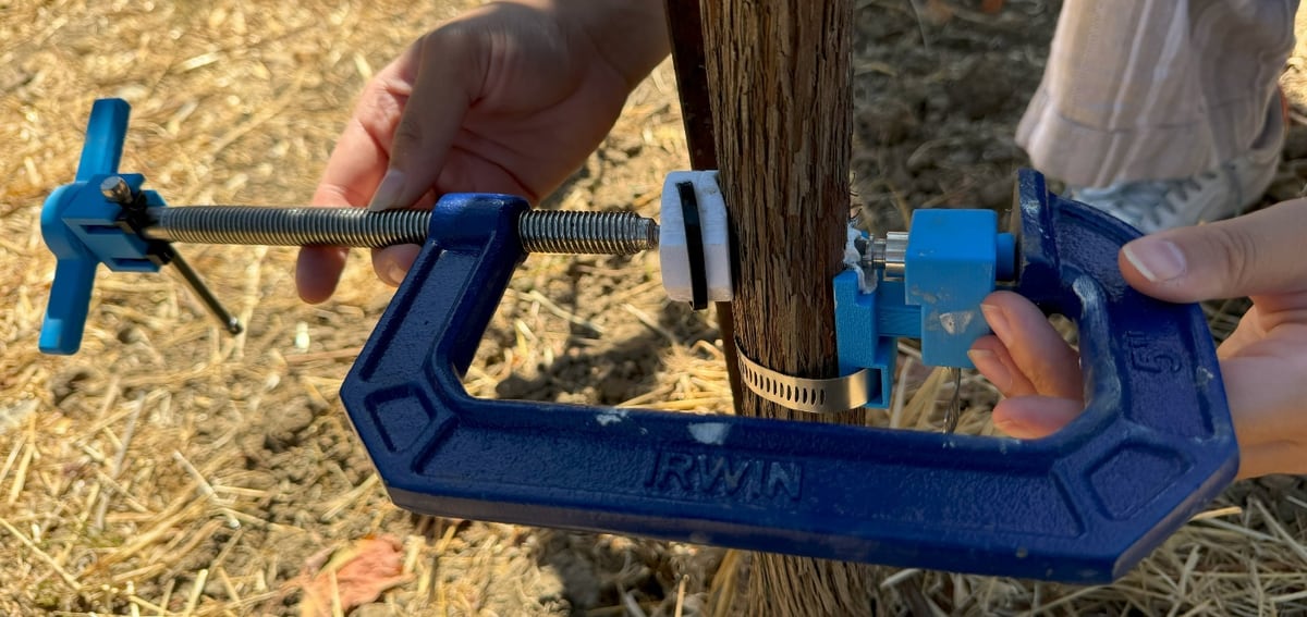 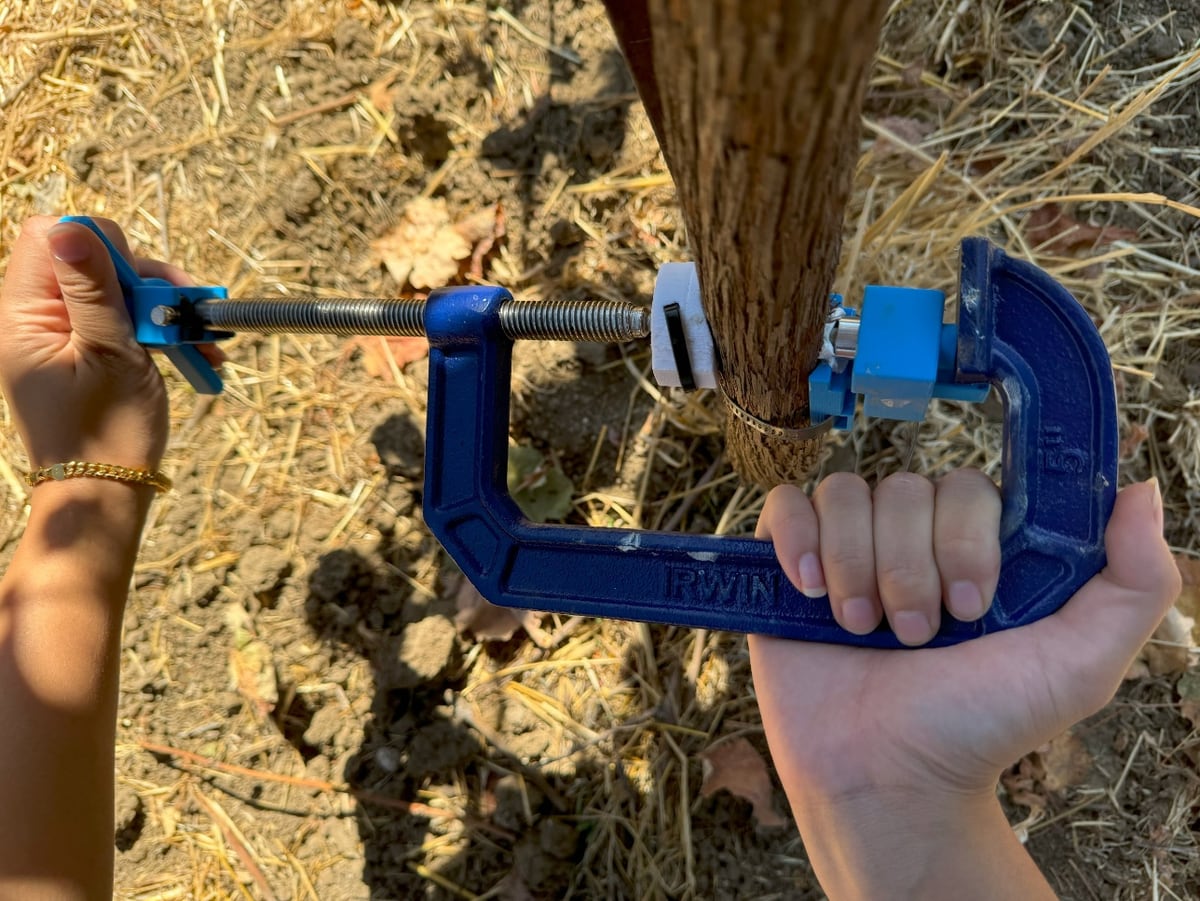 | 6. This step uses the c-clamp to press the sensor sleeve to an appropriate depth into the xylem. The c-clamp has a plastic torque-limiting handle that will set this depth. Do not let the plastic handle get noticeably hot as this will affect its accuracy. Position the c-clamp over the installation site. The clamp V-shaped attachment (white in this picture) fits the backside of the trunk and the metal flat part will push on the bracket’s ‘PRESS’ circle. Use the plastic handle (NOT the metal handle!) to tighten the c-clamp and press the sleeve into the xylem. Hold the c-clamp with one hand while you tighten with the other. Keep tightening until the plastic handle ‘clicks’, then stop. DO NOT click the handle more than once per install. It has a limited life of 200 clicks. Remove the c-clamp and bottom bracket to leave just the sleeve attached. Clean off any sealant on the bracket for future use. |
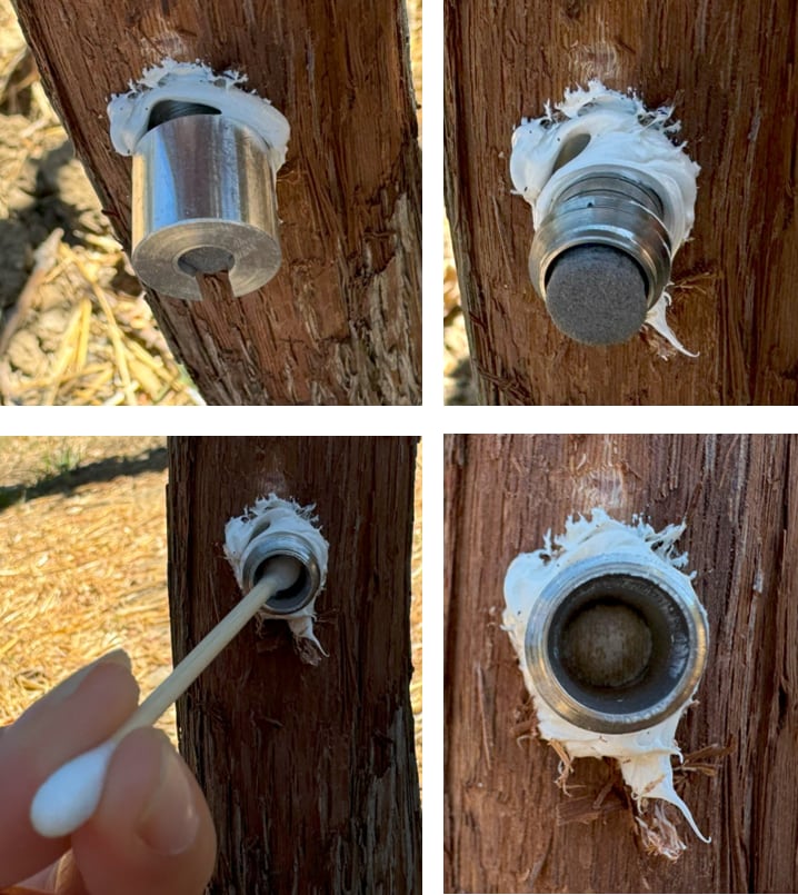 | 7. Untwist the sleeve cap to expose the foam cylinder. Use the spatula to pull out the foam. The foam cylinder should have prevented most of the sealant from coating the inner walls of the sleeve. If necessary, use a swab to remove any bulk sealant from the sleeve. Gently drill into the xylem with the provided drill bit. Drill directly through the center of the sleeve until the plastic depth stop lightly contacts the metal sleeve. |
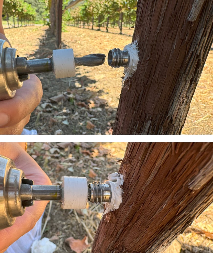 | 8. Drill into the sleeve with the included depth-limited endmill. Go slowly and let the rotation do the cutting. The hole is very shallow at only ~2 mm deep. Use the spatula from your install kit to clear any remaining debris. The hole should look bright white – abandon the install site if it looks brown or discolored. |
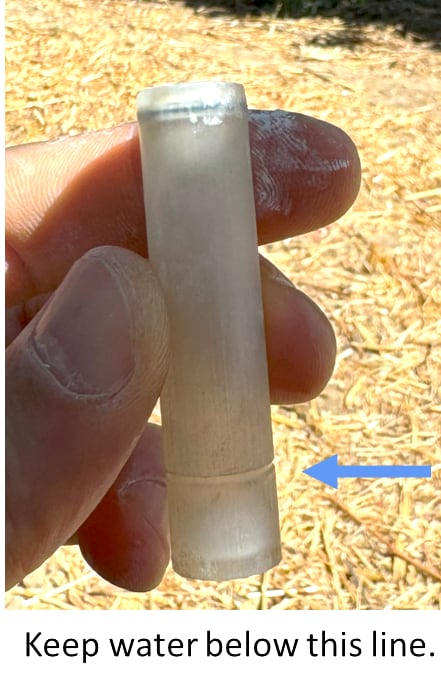 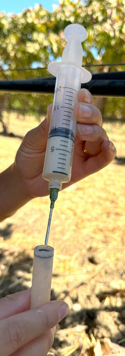 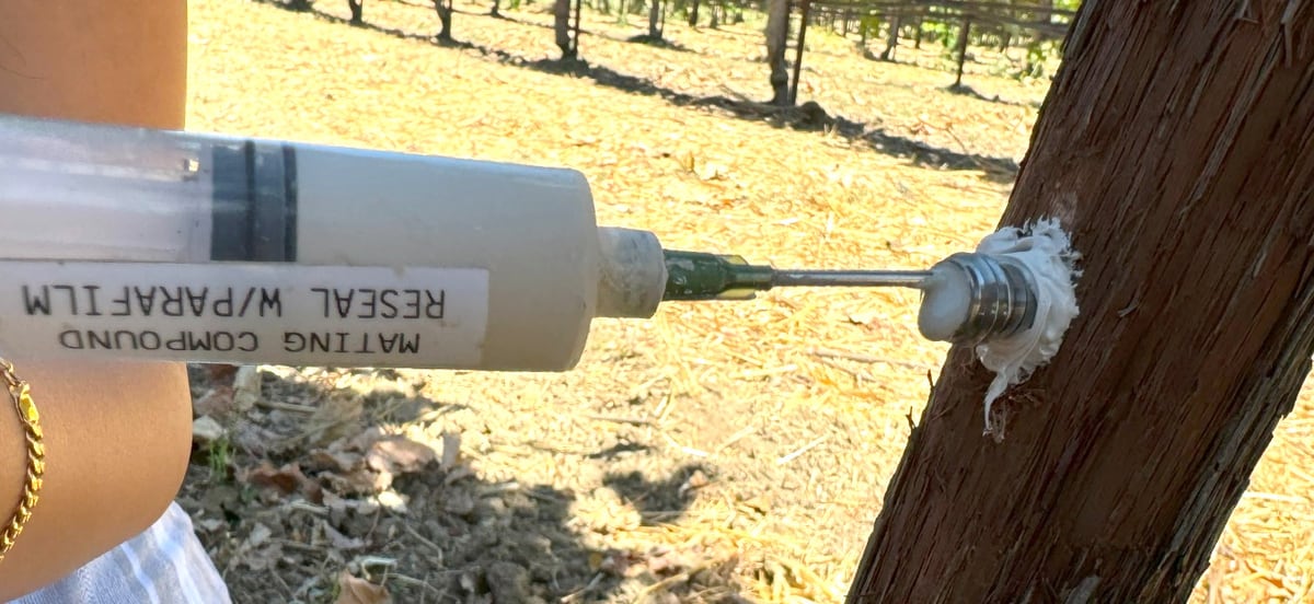 | 9. Remove the cap from the mating compound syringe and attach the needle tip. Your installation kit includes one syringe with a pre-attached tip and water reservoir. This water reservoir makes it easy to uncap and re-cap the syringe for each install. If necessary, add water to the plastic capsule, but always keep the water below the line. If the water level is too high, water will get in the mating compound and dilute it too much. Get the syringe all the way into the sleeve until it touches the xylem, and then start filling from the back. Filling from back to front prevents air bubbles. Replace the needle in the storage plastic capsule to prevent it from drying out. If the tip becomes clogged, remove it and replace it with a new tip. You may later soak clogged tips in water to clear them. |
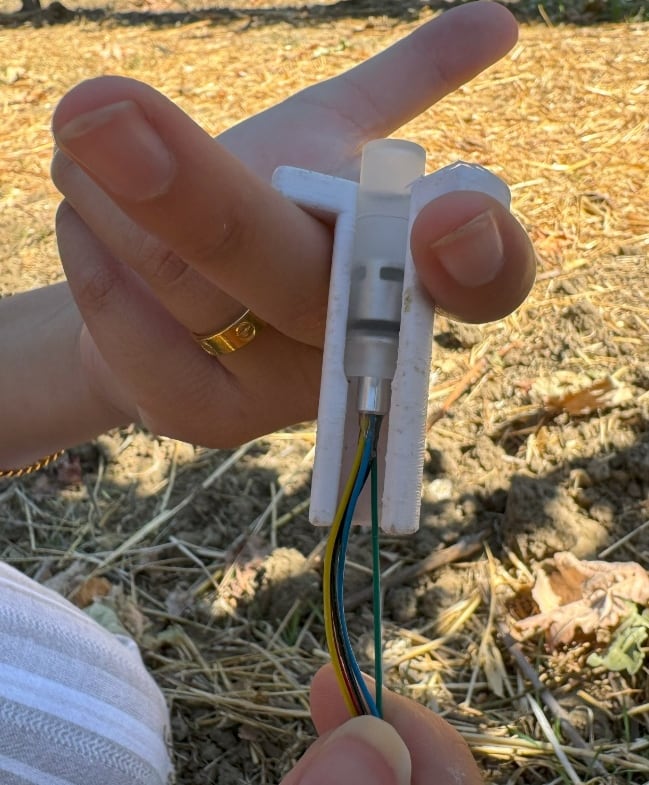 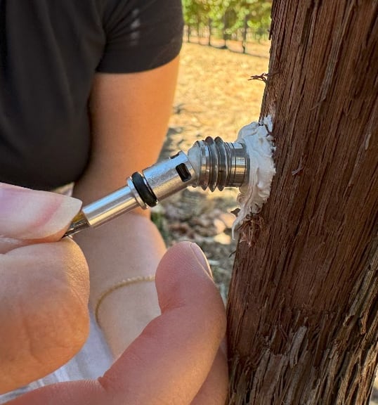 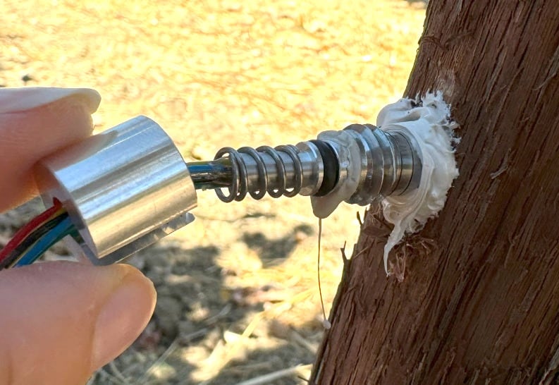 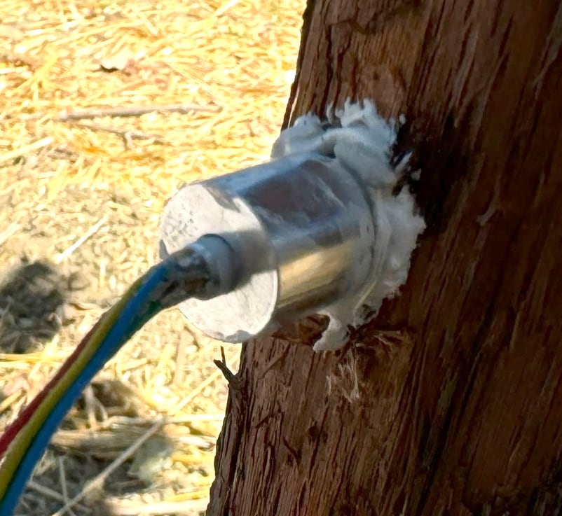 | 10. Remove the sensor plastic capsule and gently place the sensor in the sleeve. You may use the capsule puller for easier removal. The sensor will cavitate and become unusable if exposed to dry air for more than 1-2 minutes – so insert it right away. Follow with the spring and cap. The cap presses on the spring, and the spring presses the sensor towards the xylem with a controlled force. Note: handle the sensor with care. Do not touch the sensor front face, as it is easily fouled by skin oils. Sensor stuck in the capsule? Long storage or hot shipping can make the O-ring stick to the capsule wall (7mm and 3mm sensors alike). The sensor is not harmed by this. If the probe’s metal tail is accessible below the plastic capsule, hold the capsule in one hand and use needle-nose pliers on the metal tail with the other to rotate and pull. Only put the pliers on metal, never on the wires. If the tail is not accessible, use the capsule puller and pull. Do not use grease or solvent. Tighten the cap by turning it clockwise by hand until it stops. Wait a few seconds and tighten the cap further. Repeat these steps until the cap can no longer be tightened by hand. It’s important to wait because the mating compound takes time to settle in and compress so the cap can be tightened further. Clean off excess mating compound with the spatula/napkin. |
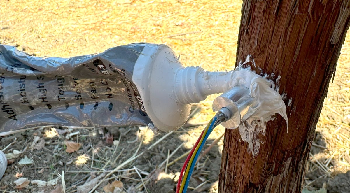 | 11. Squeeze M-1 sealant around the sensor install site to seal it against moisture. Push the sealant into the interface where the metal touches the bark. Note: if the sensor readings are consistently drier than expected and the sensor data seems to consistently drift down, the seal may have failed allowing humidity to escape. Consider replacing the sealant with fresh M-1 to fix this issue. |
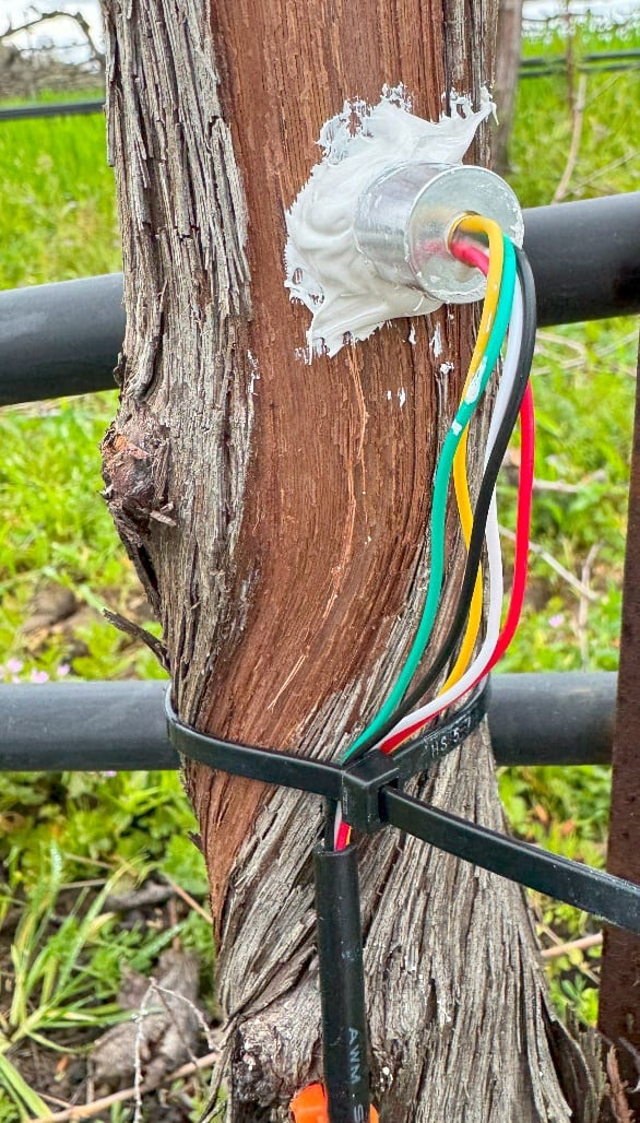 | 12. Zip tie the probe wire to the branch. This helps protect the probe from being yanked out if the cable is pulled. Zip tie excess wire against the trunk as well. Loose wire can get caught in machinery. |
| | 13. Install a second sensor into the same branch/vine for verification. Install at least 3” to the side or diagonally away from the first sensor (not directly above or below because the sensors will interfere with each other). |
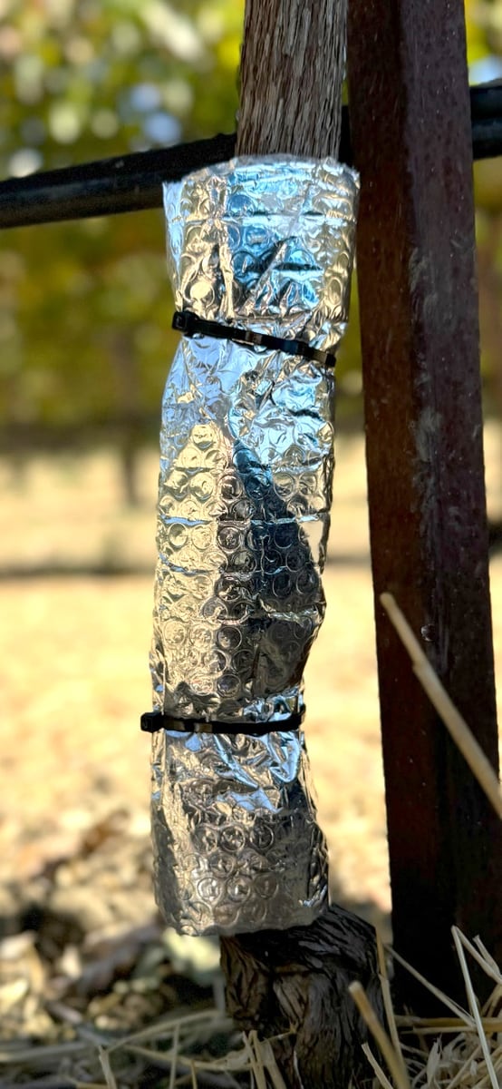 | 14. Zip tie the bubble wrap insulation around the branch. Add zip ties above and below the installed sensors. The main purpose of the insulation is to protect the sensors from sunlight and dramatic changes in temperature from sun exposure. The insulation should be attached loosely to allow condensation to dry out and prevent accumulation of water. Excess moisture in the install will hinder measurement accuracy and may lead to mold. |
Probe removal for reuse
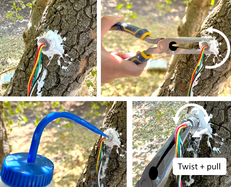 | 1. Use needle-nose pliers to unscrew the sleeve cap. Add water inside the sleeve to loosen the dried-out mating compound. Using the needle-nose pliers, grab onto the probe’s metal tail (not the wires!) and rotate the probe while pulling to extract it. |
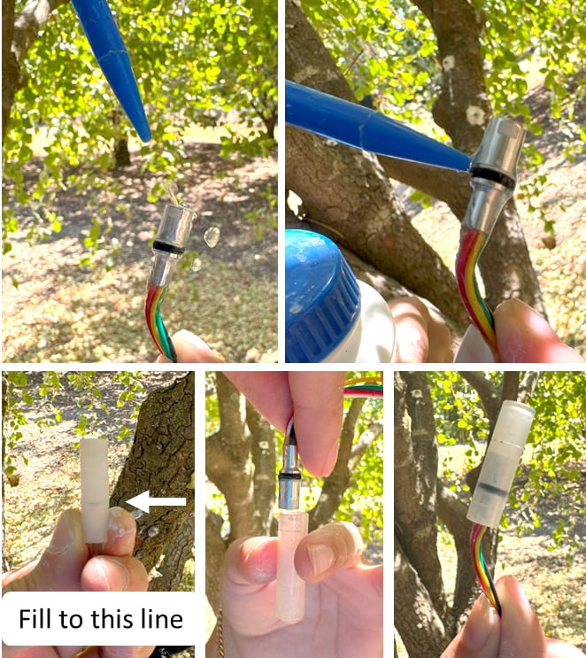 | 2. As soon as the probe comes out, squirt water onto the probe tip to wet the sensor and prevent it from cavitating. Then, squirt water on the o-ring area to clean the o-ring. The o-ring is what seals the sensor and it should be clear of debris. Fill a plastic capsule with water to the first line, then push the sensor into the capsule. Do not overfill the capsule or the sensor will not fit. |
Set up the FloraPulse datalogger
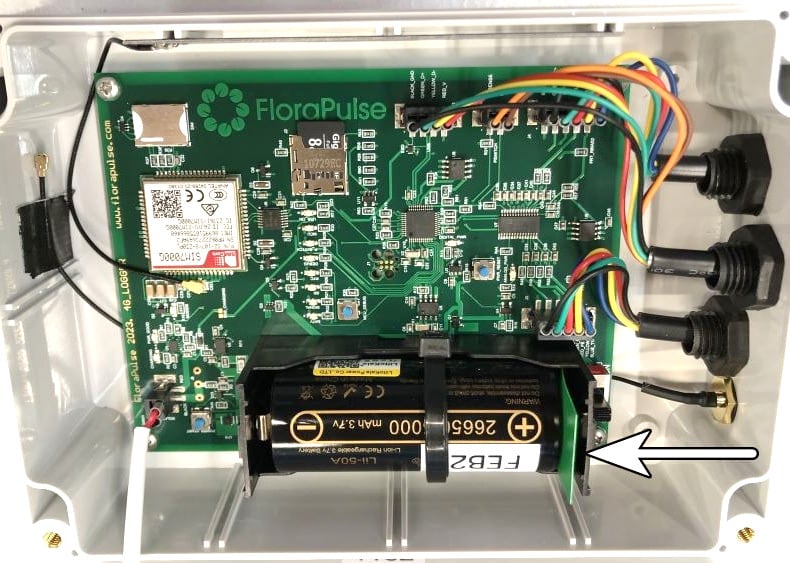 | 1. IMPORTANT – before install: using a screwdriver, open the logger and remove the plastic tab from the battery to reconnect the circuit. Flip the switch to the ON position. Note: you can complete this step inside and bring the logger to the field after. Dataloggers need cellular data to upload. The included SIM card connects to most cellular carriers in the United States. Ensure your field has some cell coverage. You can use the included USB cable and a laptop to connect to the logger and check for cellular connection. The new logger also has indicating LEDs that will show if cellular signal is found (press the ‘MCU_DEBUG’ button and wait ~5-10 minutes for the ‘SIGNAL’ LED to come on). If cellular signal is poor, you can add an external antenna to increase reception. These options are discussed in the datalogger manual. |
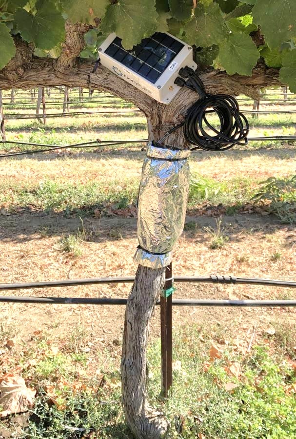 | 2. Hang the logger from a branch, facing up and toward the equator (south in the northern hemisphere, north in the southern hemisphere). Attach each corner of the logger with a small loop to two branches in a ‘Y’-shaped branch to prevent the logger from rotating. Ensure the logger will not rotate and is well-attached, with at least 3 attachment points. Alternatively, hang the logger from trellis wire or support posts. If you plan to use a shaker to harvest this tree: hang the logger from a post. Shaking the logger will break it. Ensure the logger is placed in a location that will not be harmed by machinery. |
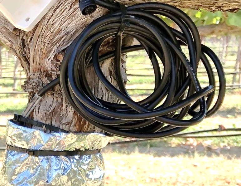 | 3. Zip tie extra wire in a loop to prevent it from catching onto machinery. |
Pressure switch installation
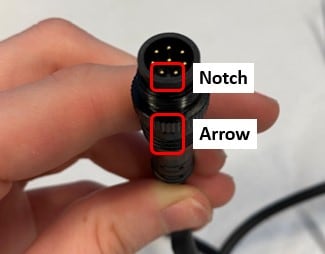 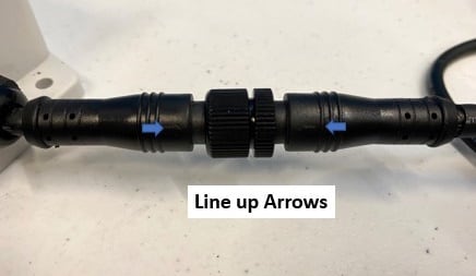 | 1. Connect the pressure switch wire to the 8-pin port on the datalogger and tighten the nuts to create a waterproof seal. Be careful to align the notch on the connectors. Do not force them together as this will break the fragile gold pins. |
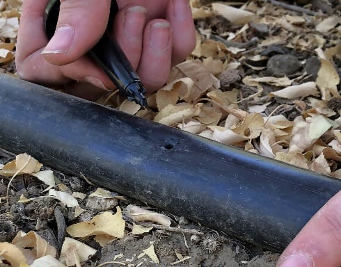 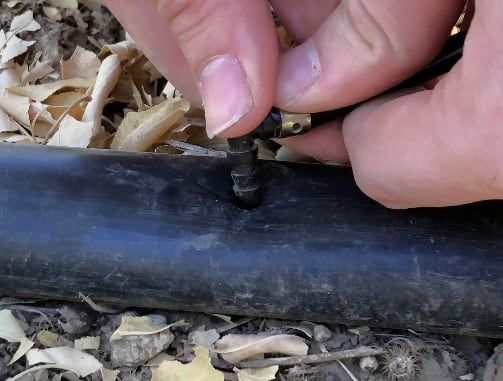 | 2. Using the provided drip punch tool, punch a hole in the nearby irrigation tubing (main line). Then push the pressure switch barb into the hole. Tip: you can use the back of the hole punch to assist you when feeding the barb into the tubing. |
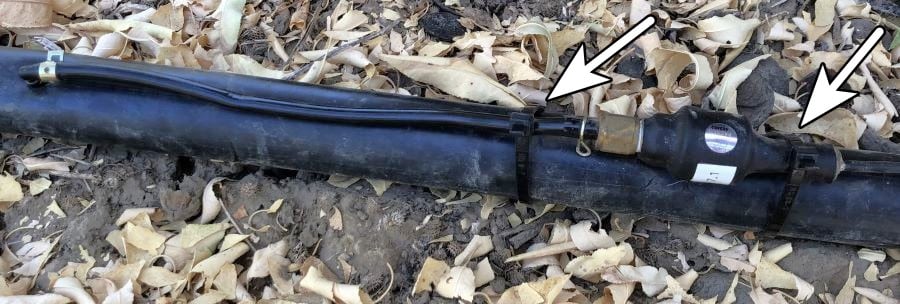 | 3. Use zip ties to attach the pressure transducer to the drip line. Then zip tie the cable tightly, following the drip line and tree trunk all the way to the logger. Tie all loose wiring so it doesn’t get caught by passing machinery. |
Protecting the system during harvest
Dataloggers should not be left on the tree when shaking or machine harvesting.
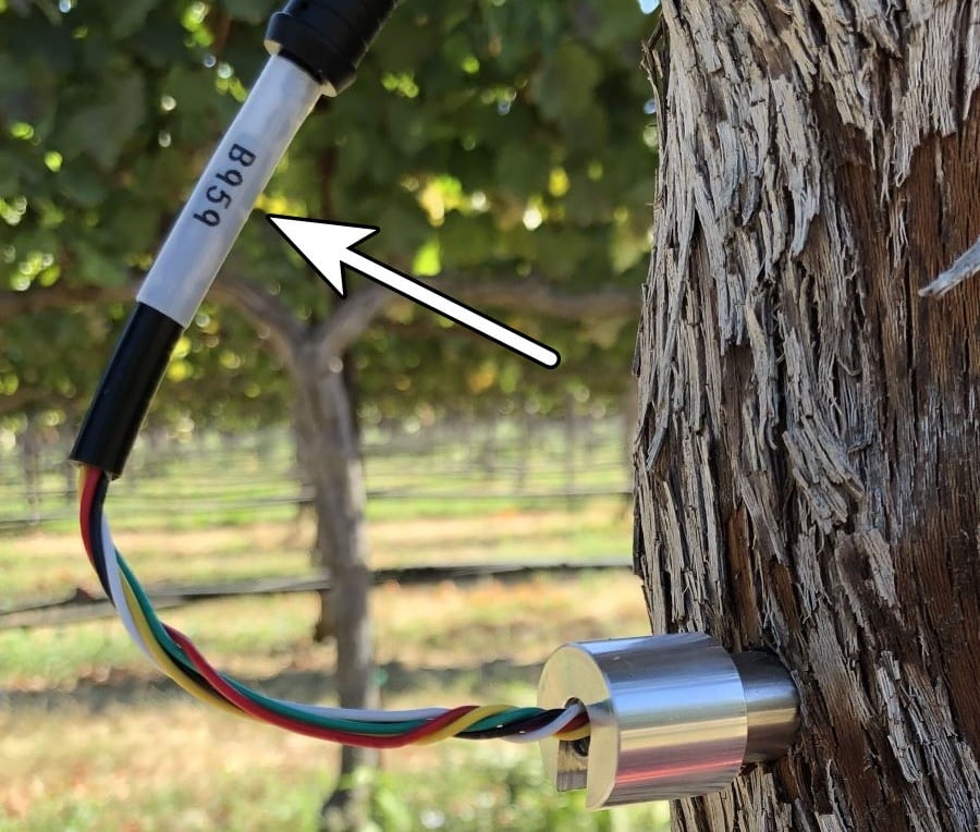
Ideally, the FloraPulse system should be installed and running continuously. However, harvest machinery may damage the logger if it is left attached during the harvest period. You can protect the FloraPulse datalogger for harvest as follows:
- Leave the sensors installed in the tree or vine. Add more covering around the sensors for protection if desired. You may use cardboard boxes or more batting for this purpose.
- You may choose to leave the datalogger attached to the probes and place it on the ground away from harvesting machinery.
- Alternatively, write down the datalogger number and which sensor is connected to each logger channel (i.e., mote #340-1 has sensor delta55, #340-2 has sensor delta57), disconnect the sensors and remove the datalogger. After harvest, mount the logger again in an area with sunlight and reconnect the sensors.
Appendix: specialized installation methods
Hammer sleeve installation
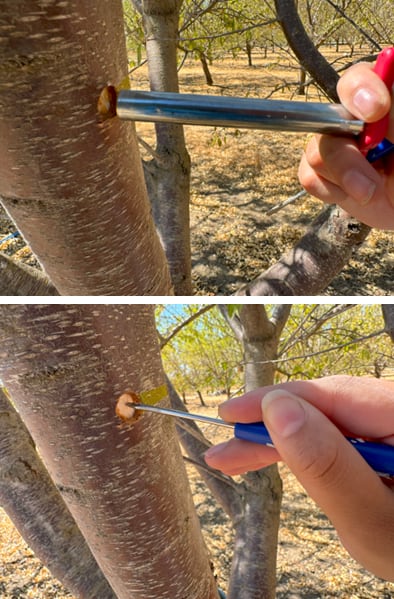 | 1. In larger branches and trunks, you may use the hammer to install the sleeve (instead of using the c-clamp). This hammer method requires a sturdy branch that will not sway when hammered, and more dexterity to accurately place the sleeve, but takes less time and may be easier in some crops. The first step is to use the cork borer to cut through the bark and phloem and get to the xylem. The phloem is usually much softer than the xylem, thus the borer will easily cut through the phloem, but struggle to cut into the xylem. The amount of force needed to cut through the phloem depends on the crop and growth stage. Use the spatula to pull out the plug of phloem. Use the spatula to scrape the exposed xylem surface. This will remove any remaining phloem and ensure a clean surface for the sealant. |
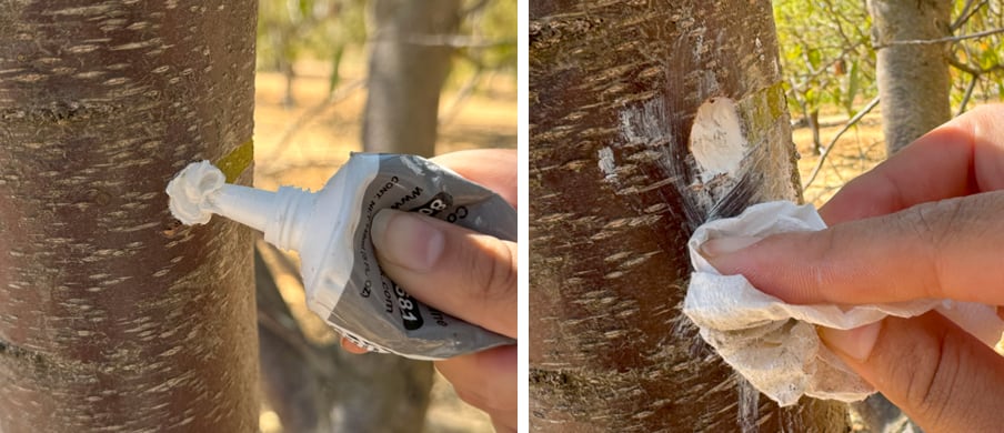 | 2. Apply sealant to the exposed xylem. Use the application tip to spread the sealant around the xylem and to ensure it sticks to the surface and there are no voids. Use a napkin to clean excess sealant around the edges of the hole. You will need to clearly see the edges of the hole to align the sleeve in the next step. |
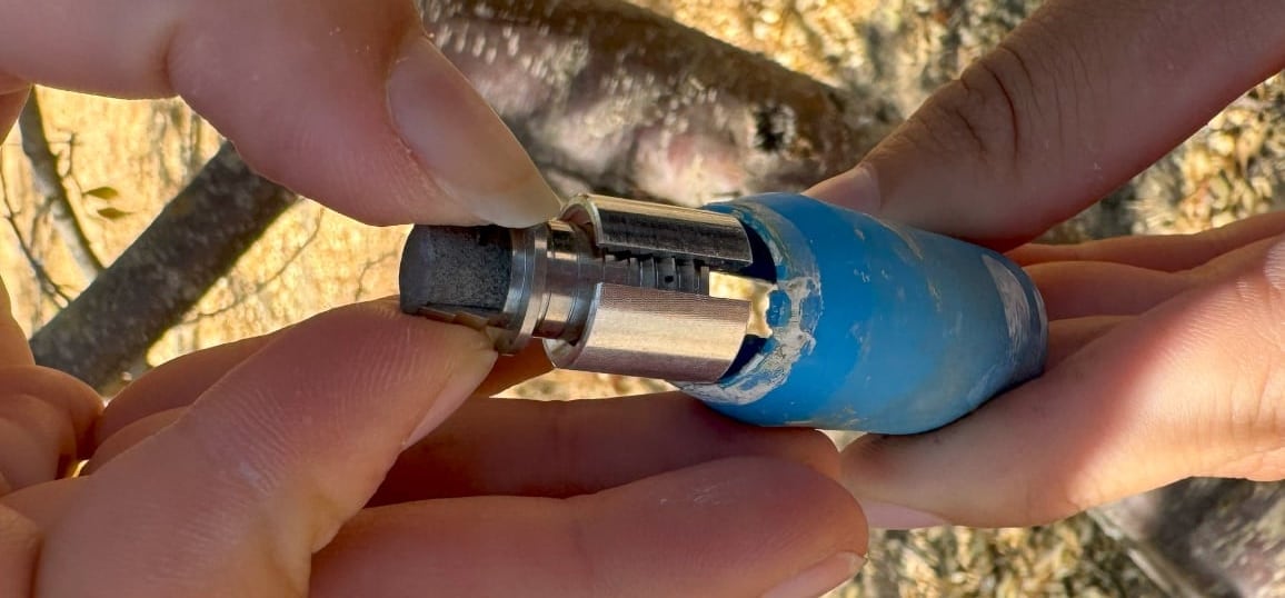 | 3. Place the sleeve cap into the plastic piston. Align the groove on the cap with the nub on the piston and push the cap in all the way. |
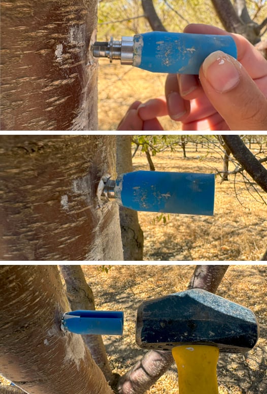 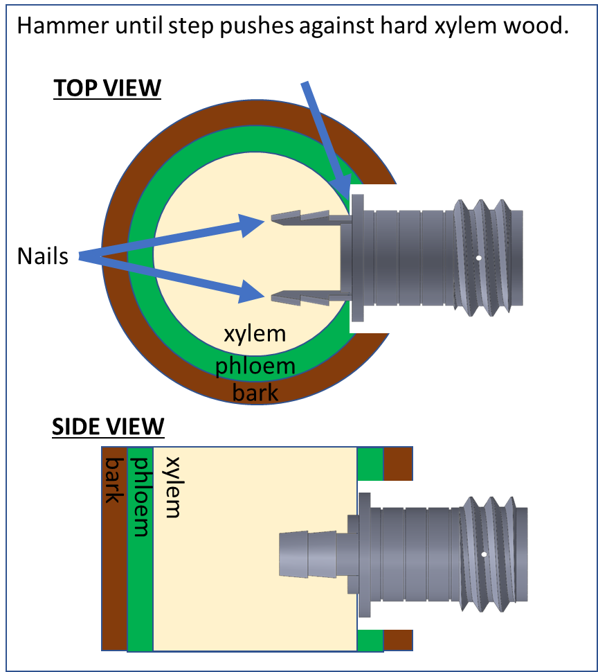 | 4. Align the sleeve in the center of the xylem opening. Rotate it so that the nails are parallel with the branch/trunk and on the sides of the hole. Push the sleeve into the hole by hand and hold it. While holding the piston, hit the backside of the piston with a mallet to drive the sleeve into the xylem. Keep hammering the sleeve with moderate force until it stops going in. The sleeve nails will easily push into the xylem, but the sleeve will stop going in when the large step presses against the xylem and prevents further movement. Once the sleeve is flush and will go no further, pull the piston to remove it and clean off any sealant from it for future use. At this point, the sleeve is firmly inserted into the xylem and you can continue from step 7 of the install instructions (untwist the sleeve cap) onwards. 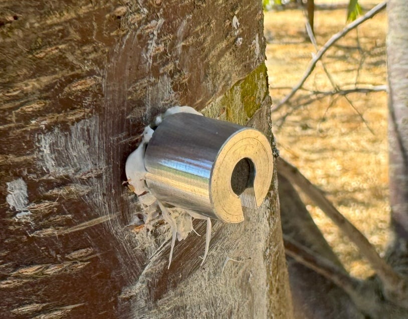 |
Thick bark installation
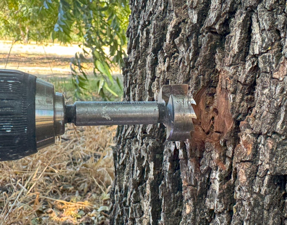 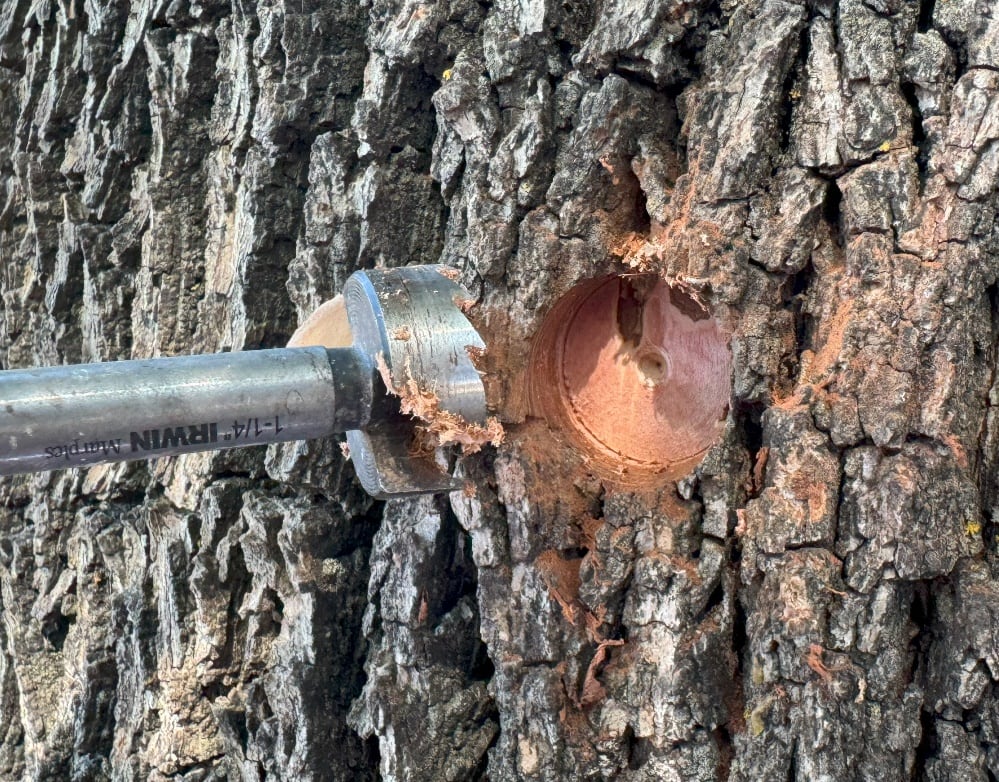 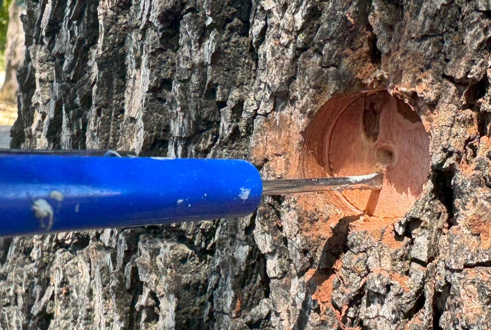 | 1. Here are instructions for installing the 7mm microtensiometer probe into a tree with bark thicker than ~1 cm. This method is similar to the hammer method above, but requires first drilling through the bark to perform the typical installation. First use the 1-1/4” forstner bit to drill through the rough bark until you hit the softer phloem underneath. The phloem will usually look lighter in color and should be softer. Once in the phloem, use the included spatula to measure the thickness of the phloem layer. The spatula will cut through the phloem, but not into the xylem. Drill and measure until the thickness of the phloem layer is ~3 mm. |
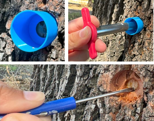 | 2. Place the plastic cork borer guide in the drilled hole, then use the cork borer to cut a hole through the leftover phloem. The cork borer guide will help you get a nicely centered hole. Use the spatula to remove the phloem plug, then scratch the xylem surface to shave off any leftover phloem and bring out a fresh xylem surface for best adhesion. |
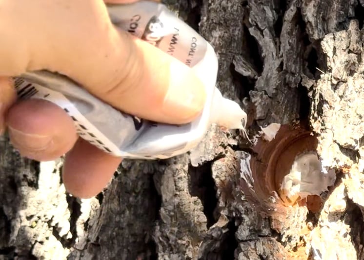 | 3. Apply M1 sealant inside the inner hole, on top of the xylem. Use the applicator tip to spread around the glue and ensure it adheres to all the surfaces and there are no voids. |
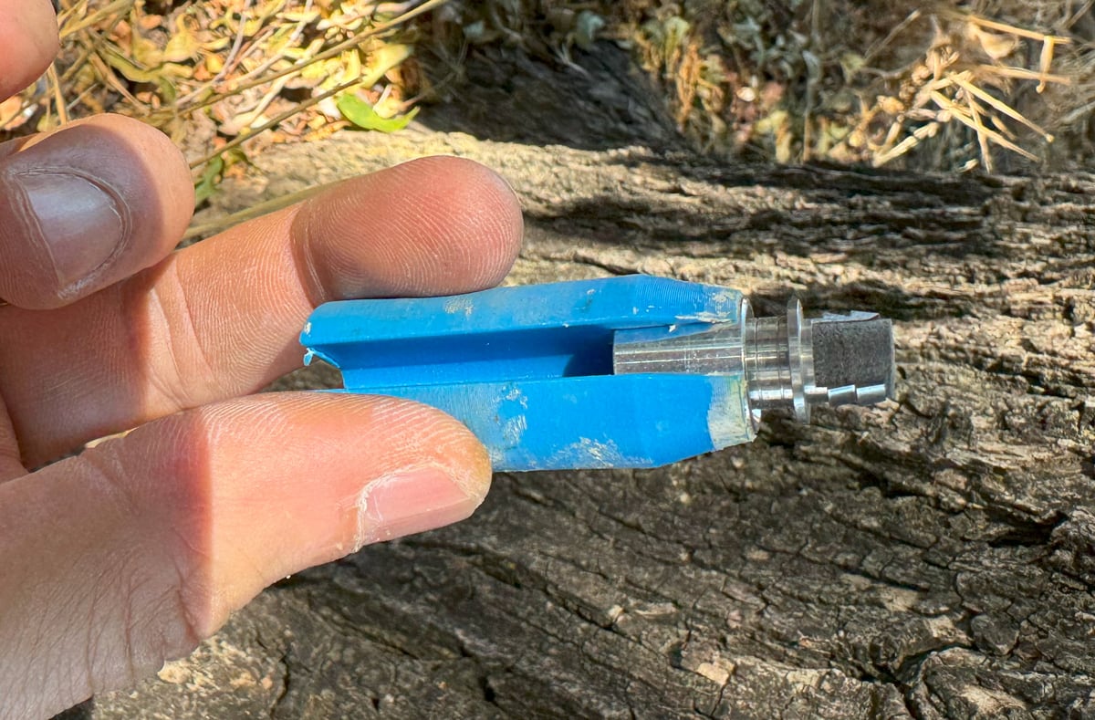 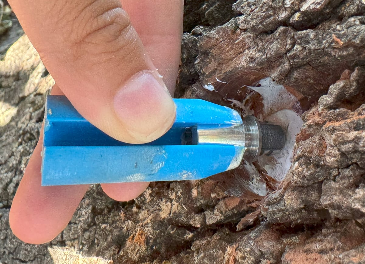 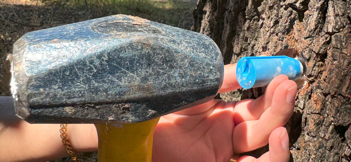 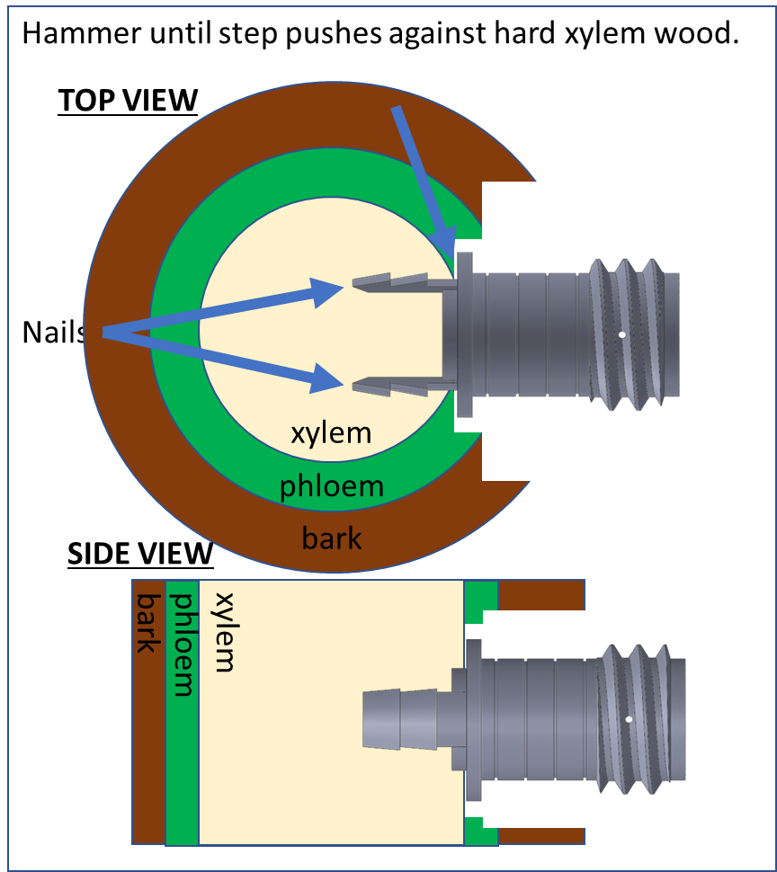 | 4. Place the sleeve and cap in the piston. Align the groove on the cap with the groove on the piston. Align the sleeve and manually push it into the hole and glue. The sleeve nails should be aligned vertically and on the sides of the hole. Hold the piston with one hand and hit it with a hammer to push the sleeve into place. The nails and front part of the sleeve will go into the xylem, but the sleeve will stop going in once the sleeve step pushes against the xylem. Continue hitting the piston with moderate force until it no longer advances into the xylem. The sleeve step will push the M1 adhesive out of the way and make a seal against the xylem. |
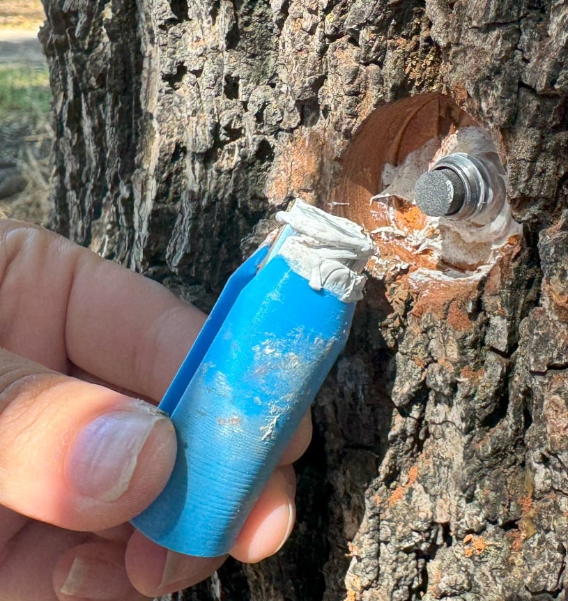 | 5. Rotate the piston to unthread the cap from the sleeve. |
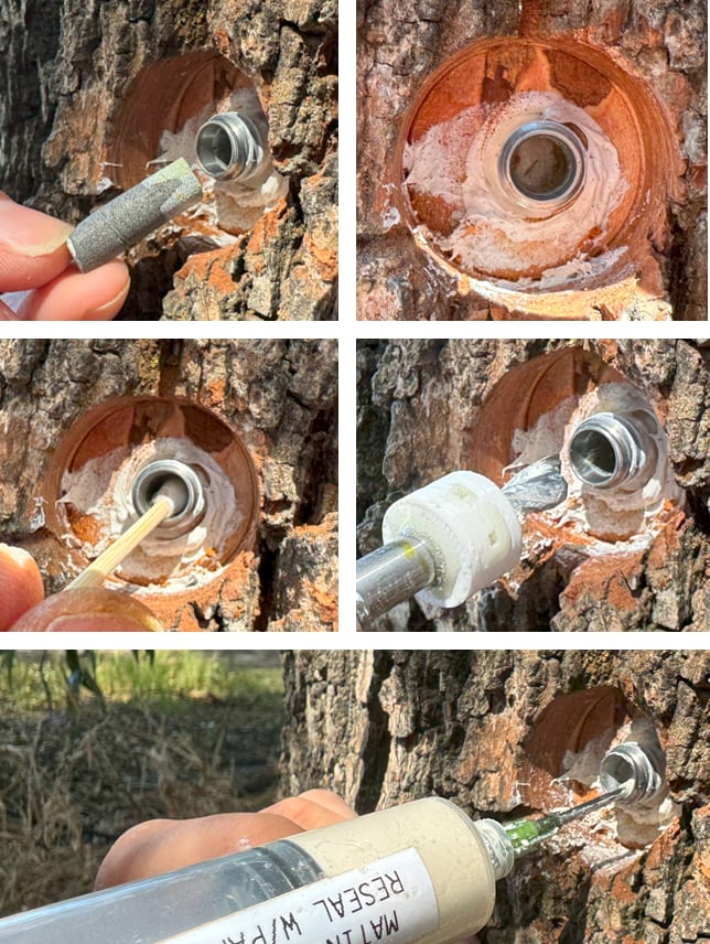 | 6. Follow steps 7 to 9 of the install instructions to remove the foam, remove any excess sealant from inside the sleeve with a swab, drill into the sleeve and add mating compound. |
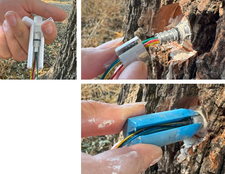 | 7. Remove the probe from the capsule, then quickly insert it into the sleeve. Use the cap to push on the spring, and the spring will push the sensor in with calibrated force. You may use the piston to help thread the cap onto the sleeve. |
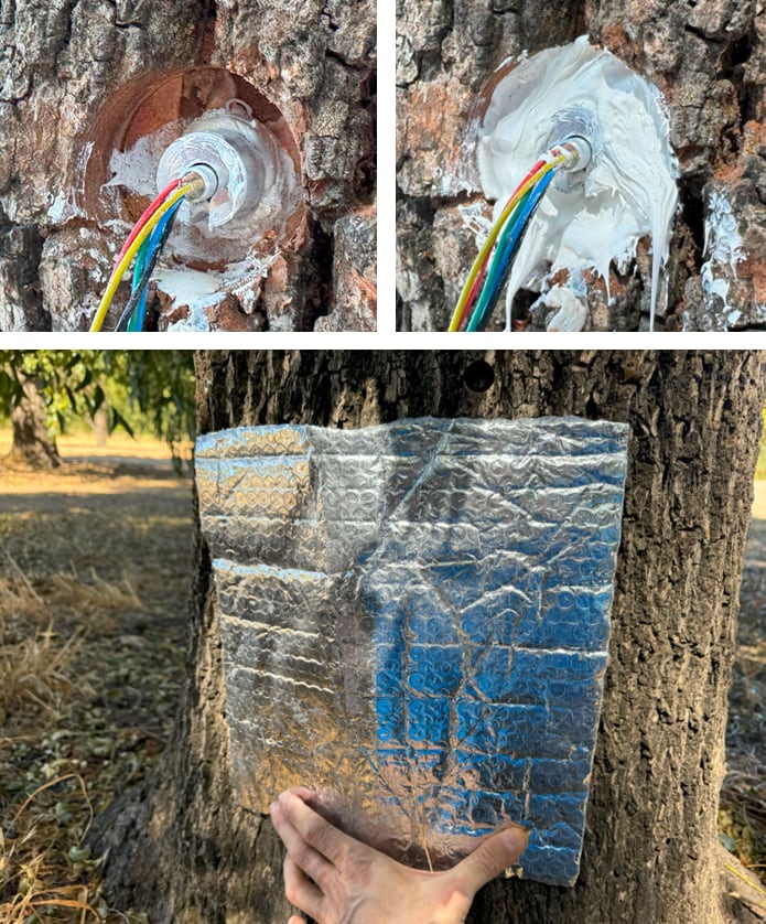 | 8. Seal the rest of the hole with M1 sealant. Add the insulation, loosely, on top of the sensor. The main purpose of the insulation is to protect the sensors from sunlight and dramatic changes in temperature from sun exposure. The insulation should be attached loosely to allow condensation to dry out and prevent accumulation of water. Excess moisture in the install will hinder measurement accuracy and may lead to mold. You may use a nail or staple gun to fasten the insulation on top of the sensor. Zip ties can work, but you will need to chain many ties together to reach around a wide trunk. |
Walnut installation
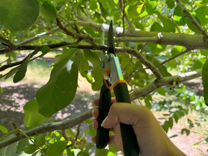 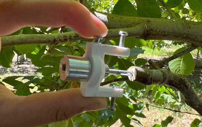 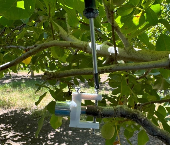 | 1. In walnut, it’s necessary to install the microtensiometer sensor into the pith of a branch, to avoid the tree’s wounding response from flooding the sensor. First, pick a branch for cutting and installing. You want a branch that has leaves and is near other branches with leaves, to ensure it will have continuous water flow, and about 10-15 mm in diameter. Cut the branch with shears, leaving a clean and flat surface for installation. Test installing the sleeve into the pith hole in the center of the cut. The sleeve nose should glide in smoothly without too much resistance. If the pith is too small, cut another branch and try again. Press the sleeve in all the way and secure the bracket with the screws on each side. Tighten the screws so the bracket is firmly attached, but don’t overdo it or the plastic will break. |
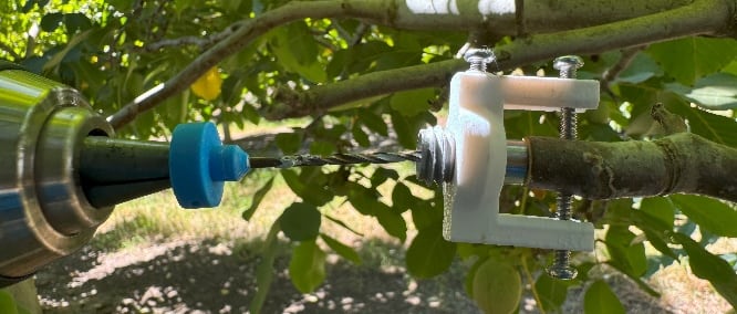 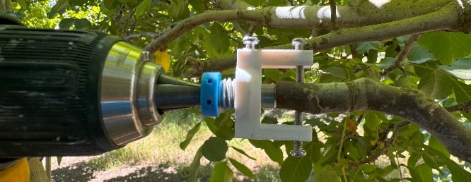 | 2. Drill into the sleeve with the included bit. |
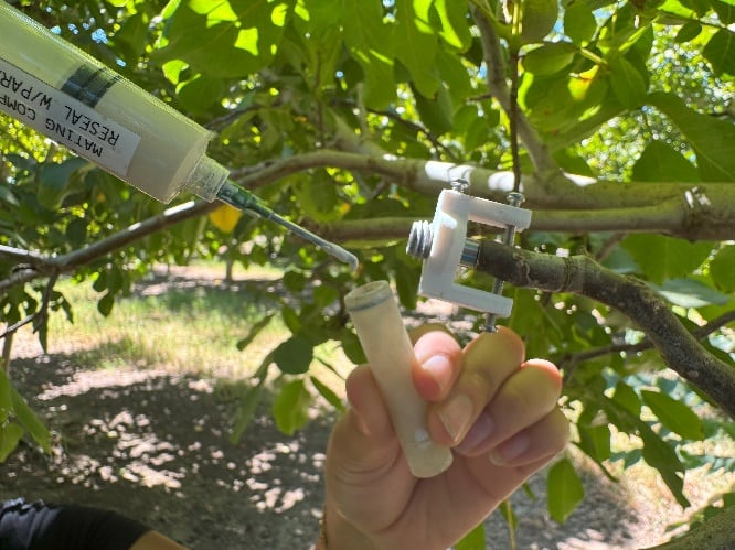 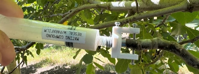 | 3. Apply mating compound into the sleeve nose and body. Push the syringe all the way into the nose and press to fill the nose from the end and avoid bubbles. Pull back the sleeve as you fill until the whole sleeve and nose are full of mating compound. |
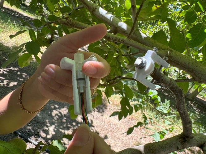 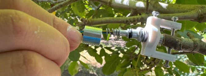 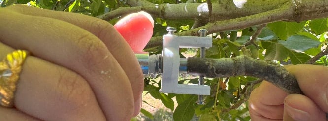 | 4. Pull the sensor from the capsule and quickly insert it into the sleeve. Use the cap to press on the spring and the spring will push the sensor into the sleeve with a controlled force. Thread the cap as far as it will go. |
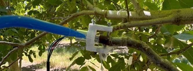 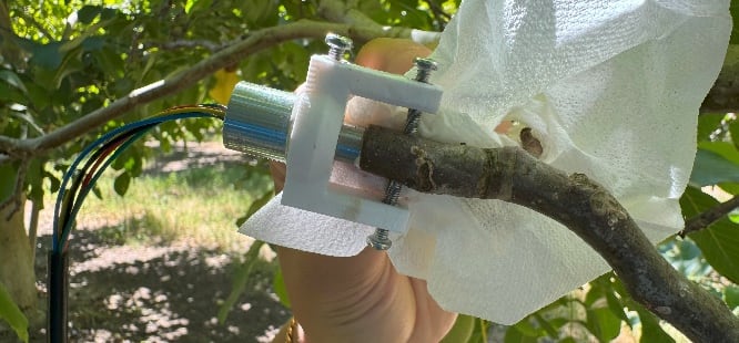 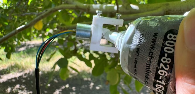 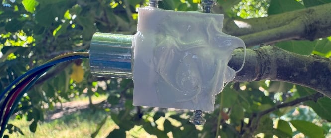 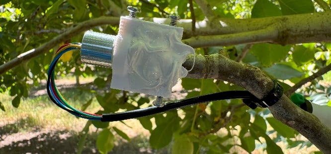 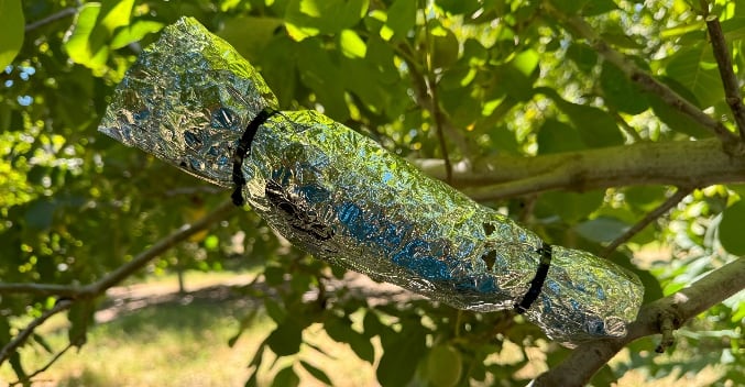 | 5. Use water to clean off any mating compound that exits through the seam between the sleeve and branch. Then dry off moisture with a napkin. A clean, semi-dry surface will ensure that the sealant adheres and seals properly. Apply sealant to the sleeve and branch, pushing into the surfaces to ensure it adheres and there are no voids. Zip tie the probe onto the branch. Zip tie batting insulation around the probe. The insulation should be attached loosely to allow any accumulated water to evaporate. |