
Sensor re-use and test manual
For advanced users — removing, cleaning, storing, refilling, testing and re-installing FloraPulse probes
720 Olive Dr Ste E
Davis CA, 95616
(530) 220-7668
This guide provides written instructions for removing and re-using the FloraPulse probes. We recommend watching the videos below for a complete overview of the process.
Links to installation videos
- Default installation video
- How to remove/reuse probes
- Installation into thick-bark trees
- Sensor dry-out test and sanding the pores
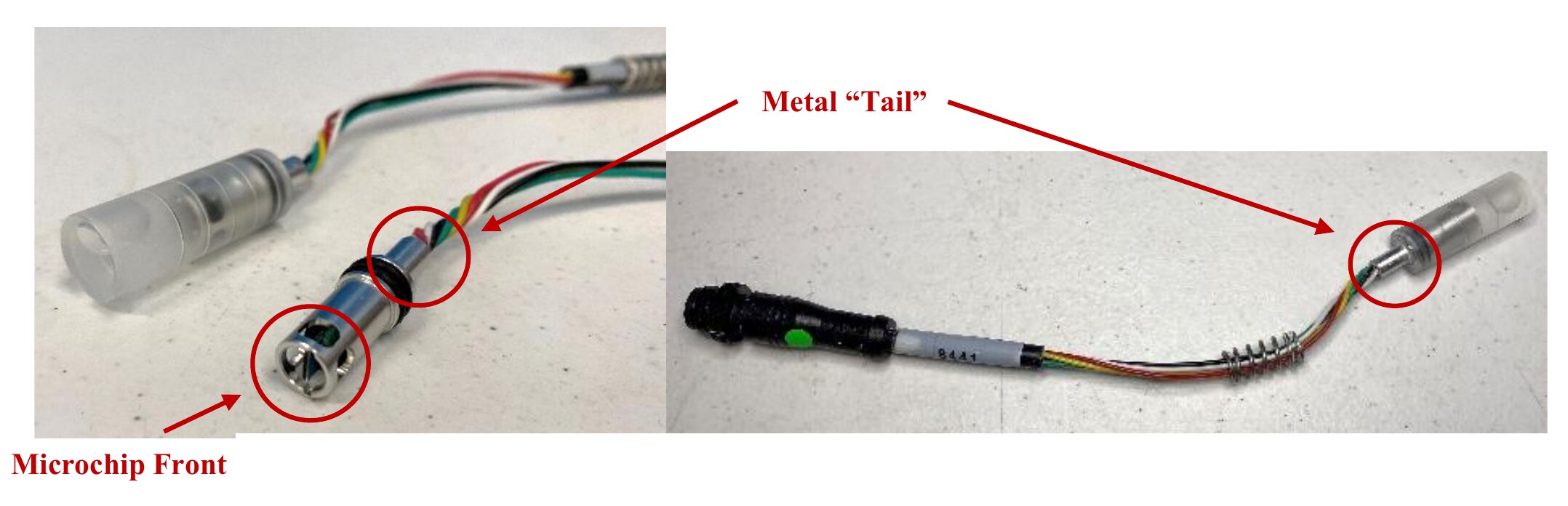
The microchip front is the sensing face. The metal tail is the body you may grip with pliers. The microchip front must be kept wet and away from contaminants throughout removal, storage and re-install.
Store sensors in DI (deionized) water — never tap water. Tap water carries dissolved minerals, chlorine and microbes that can foul the nanopores in the sensing face. Wherever this manual says to keep, soak or store the sensor in water, use DI water. Tap water is fine for cleaning the install site and loosening the cap threads, where it does not reach the sensor face.
General instructions
FloraPulse sensor installations are generally permanent, but it is possible to remove, store and reinstall sensors. Keep in mind the sensors are fragile and can break during removal. It is best to only move sensors when necessary, and to do so very carefully.
There are 3 main reasons for removing a sensor — here is what we recommend for each.
- Poor installation performance. If the sensor appears to be reading erratically, or values that are too low or too high, this could be caused by issues with the installation. In this case we recommend the sensor be removed, stored, tested in the laboratory, then re-installed in a new tree.
- Move to a fresh installation site for the 2nd+ season. We have seen that, at least in some crops such as almond, the sensor becomes less responsive when used for a second season in the same installation site. We believe this happens because the install site closes off slightly during winter. For best performance, sensors should be moved to a new site each year at the beginning of the season.
- Storage during a cold winter. Installed sensors can tolerate temperatures down to 0 °C (32 °F), but if temperatures go below freezing for extended periods the sensor's water will freeze and break the sensor. We thus recommend that sensors be removed and stored in regions where temperatures regularly drop below freezing. The sensor can then be re-installed in the spring.
Removal and reuse tools
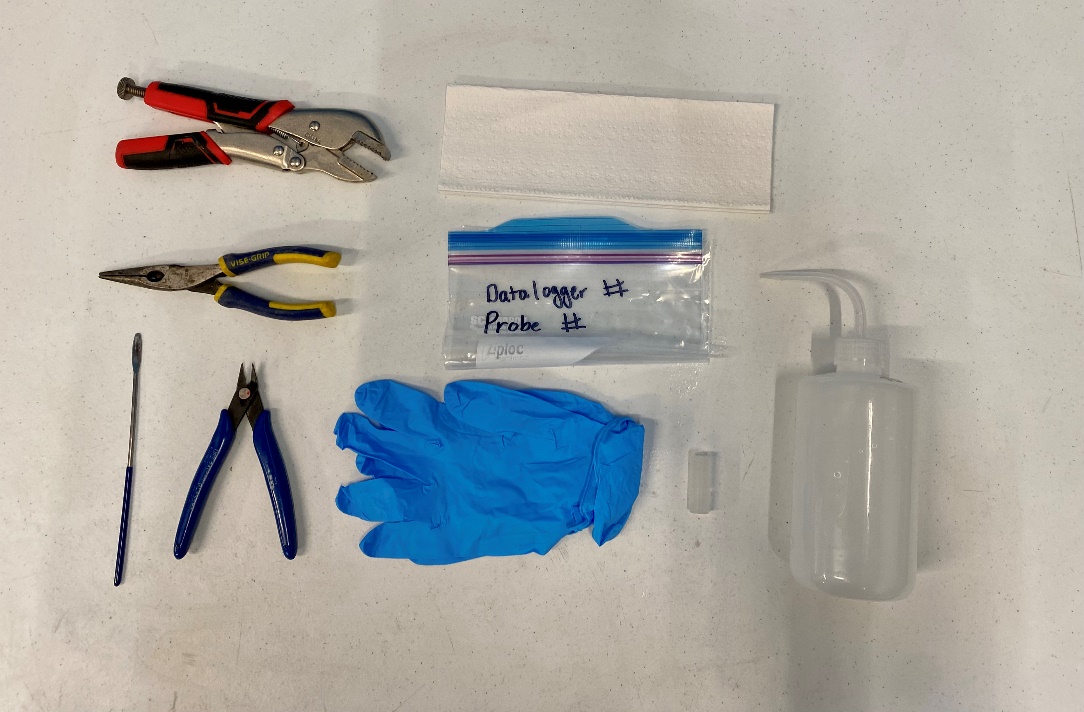
Sensor removal tools
- Vise grip
- Wire cutter (from install kit)
- Spatula (from install kit)
- Extra capsule
- Wash bottle
- Needle-nose pliers
- Labelled Ziploc bag (optional)
- Nitrile gloves (optional)
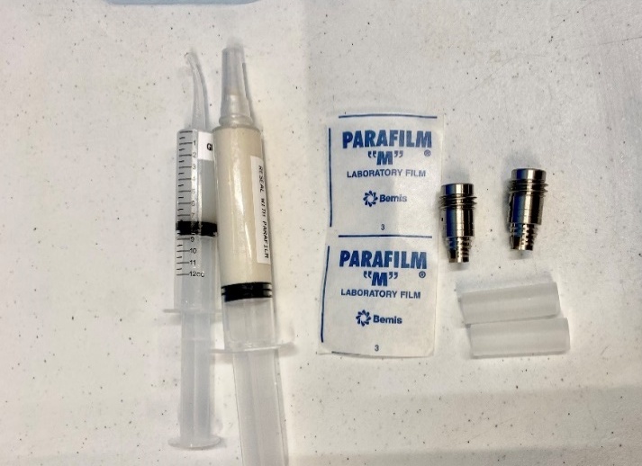
Extra sleeves, capsules and parafilm come in your install kit. After install, reseal the mating compound to keep it from drying out. These supplies are used again when you reinstall, so keep track of them.
How to remove, clean and store sensors
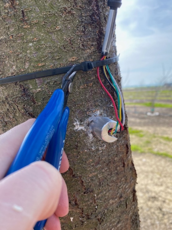 | 1. Carefully cut down the surrounding insulation/wiring. |
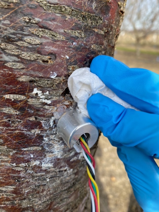 | 2. Using a napkin, clean off the excess grease and wounding gels from the install site. A clean area will help prevent contamination of the probe upon removal. You may apply water to help clean the area. |
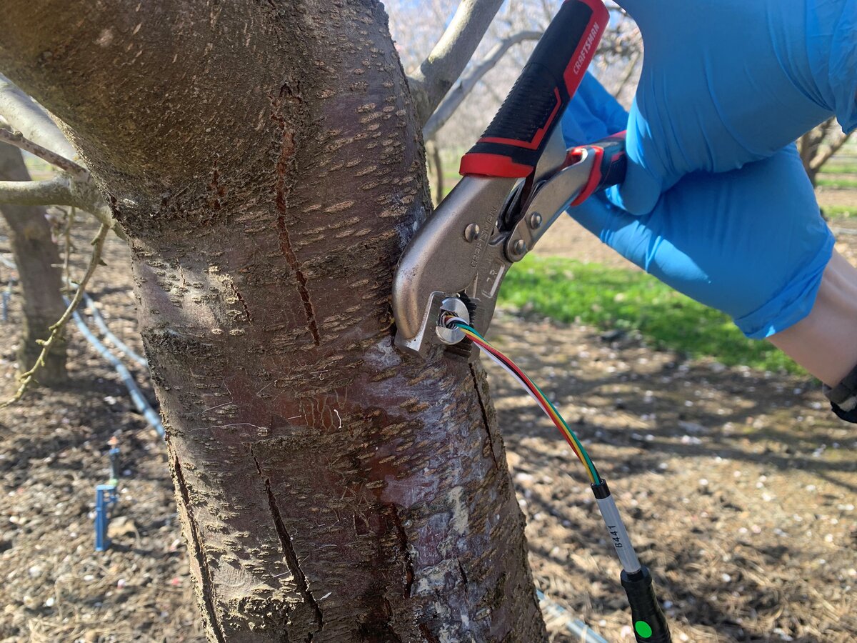 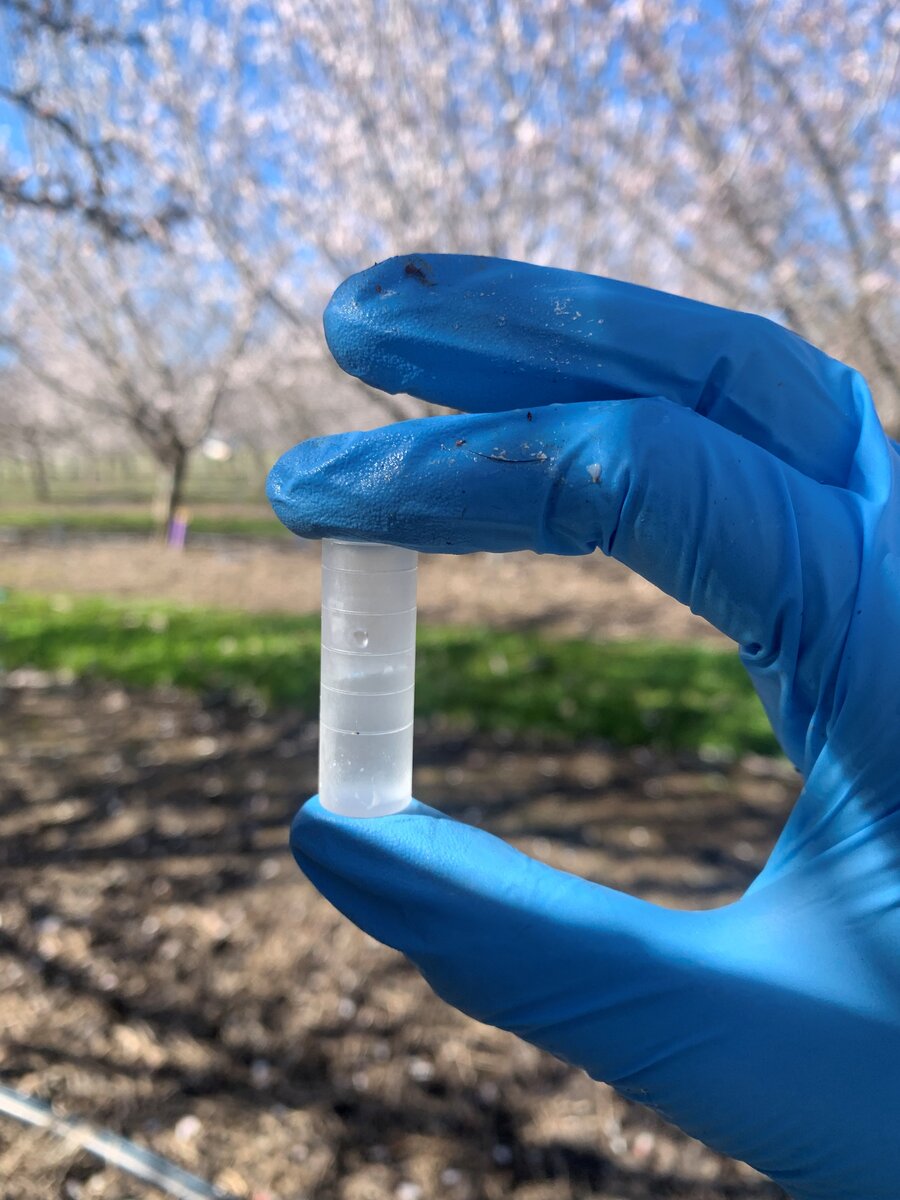 | 3. Using your hands, twist off the cap. Squirting water on the threads can help loosen the cap. If necessary, use a vise grip to remove the cap. Keep the cap for the sensor re-installation. Fill an extra capsule with DI water and set aside. The capsule should be filled to below halfway, leaving space for the sensor and an air gap. |
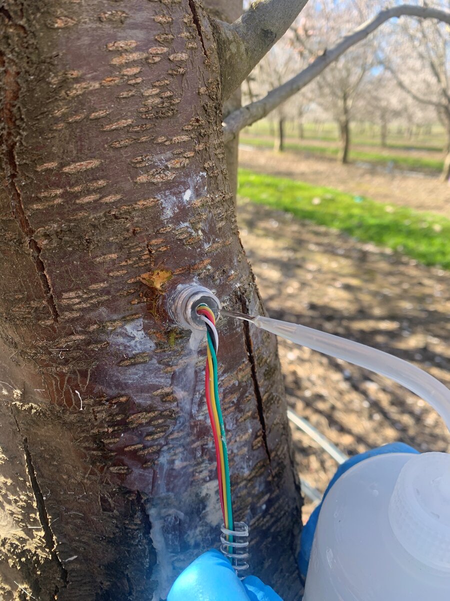 | 4. Once the cap is off, rinse the sleeve interior with water to loosen the dried mating compound. |
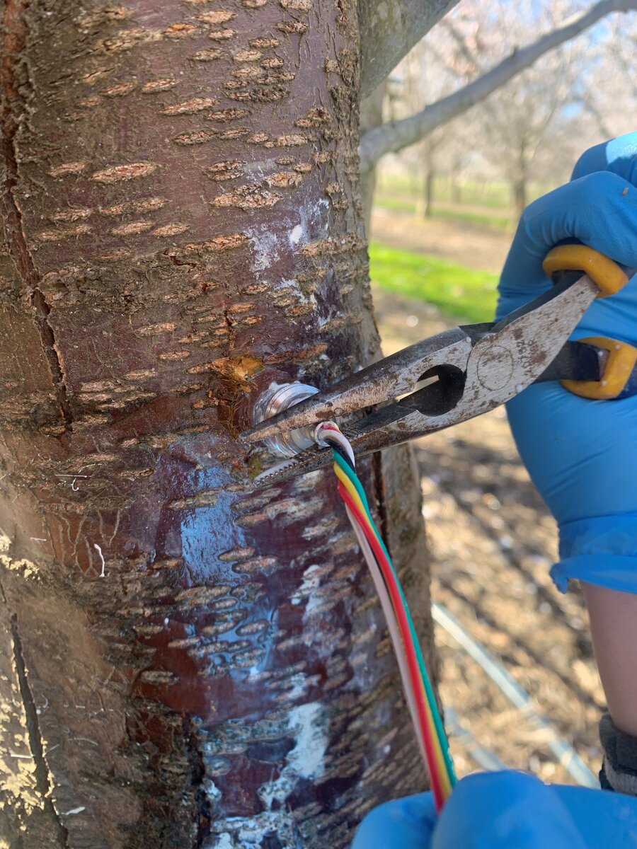 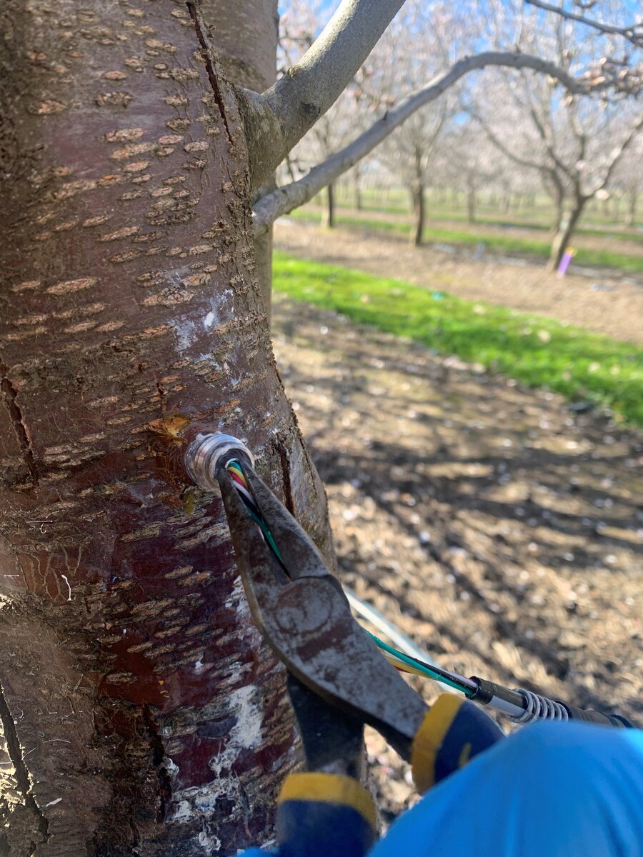 | 5. To remove the probe, try pulling on the wires by hand (gently, or the wires will break) to see if the sensor is loose and will come out easily. If the sensor is stuck, use needle-nose pliers to gently pull on the metal 'tail' base of the probe and remove the sensor. Do not pull on the wires with pliers. |
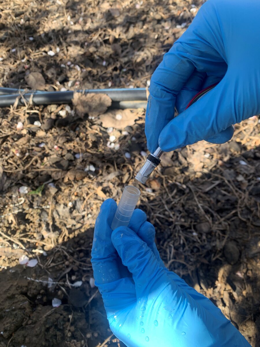 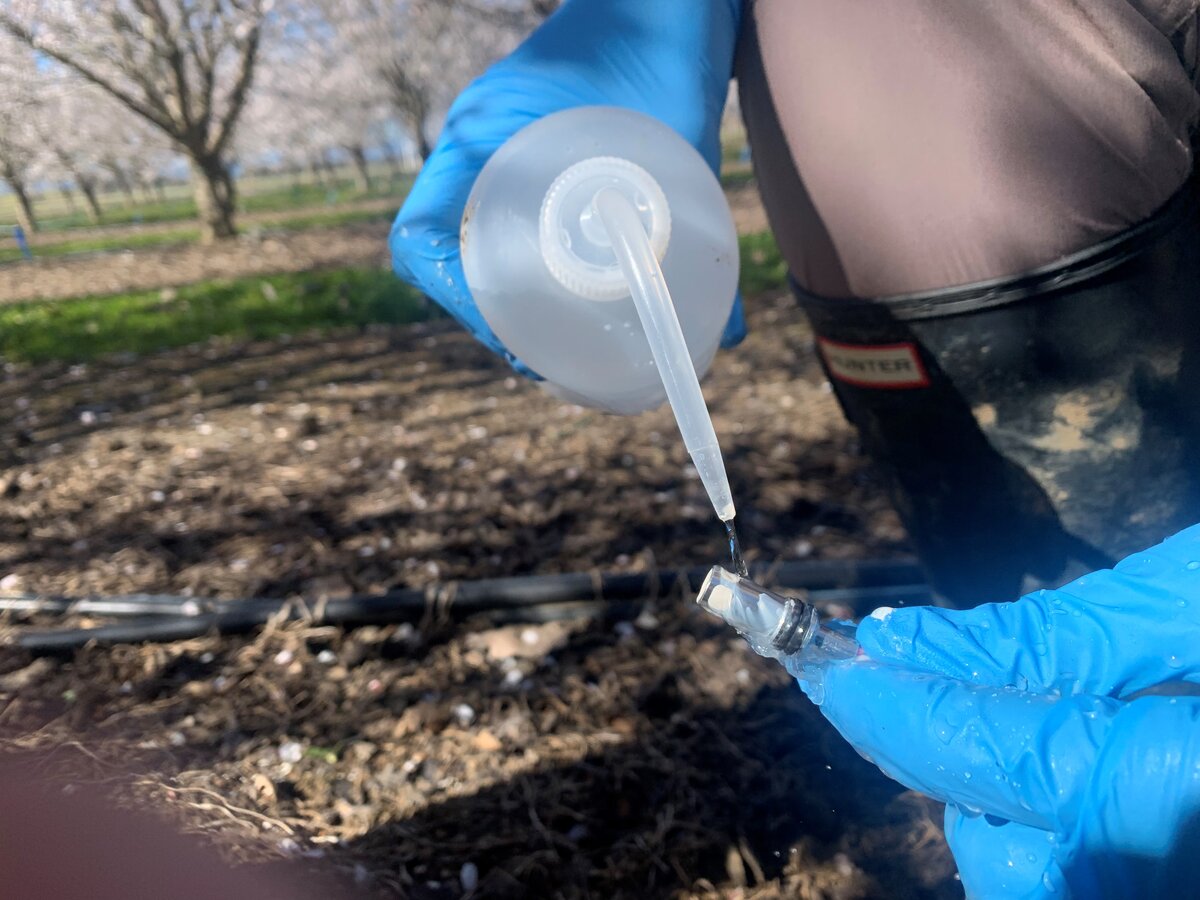 | 6. Pull the sensor straight out, and quickly place the sensor inside the plastic capsule with DI water. You may want to rinse the sensor with a stream of DI water before capping. Keep the sensor front wet and in DI water as much as possible. |
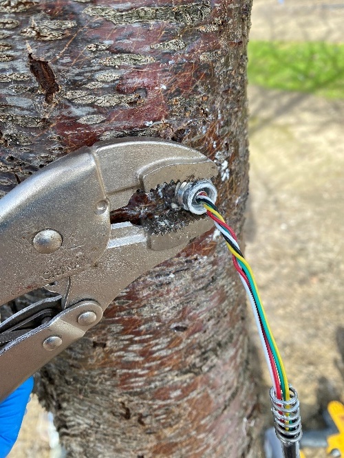 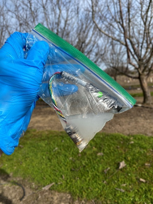 | 7. Some installs, especially older ones, can get very dry and stuck. If the sensor still won't come out, fill a container (in this case a Ziploc bag) with DI water. Using your vise clamp, grip the sleeve and pull the sensor and sleeve straight out together. Try to avoid moving/wiggling the sleeve, because this places stress on the probe microchip. Place the sleeve and sensor inside the DI-water-filled container and keep it in DI water until the sensor can be separated. Water hydrates the dried mating compound and the sensor will come loose. |
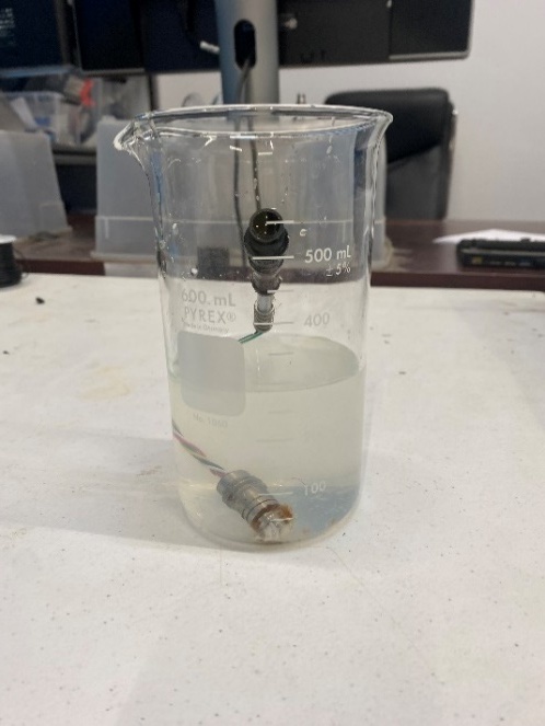 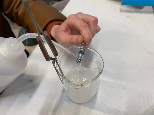 | 8. Leave the sensor in DI water to loosen the excess powder, then gently rinse it using a stream of DI water. |
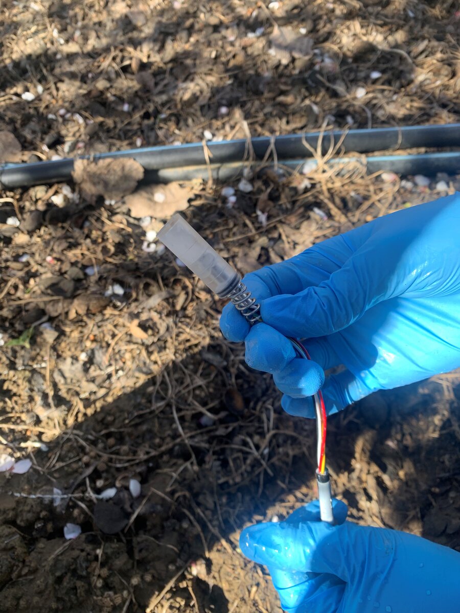 | 9. After the sensor is removed and cleaned, cap your sensor and put it aside. You may choose to label the sensor with the datalogger #, port # or anything else to help keep track of where the probe should be reconnected if needed. Sensors must be kept in DI water (not tap water) at all times. |
How to refill (re-hydrate) a cavitated sensor
If a probe cavitates (suddenly jumps to ~0 bar and stays there), you can often bring it back by refilling it under pressure. The steps below are simple and focus on avoiding air and keeping everything wet.
A. Parts to buy (DIY refilling station) — about $270 USD
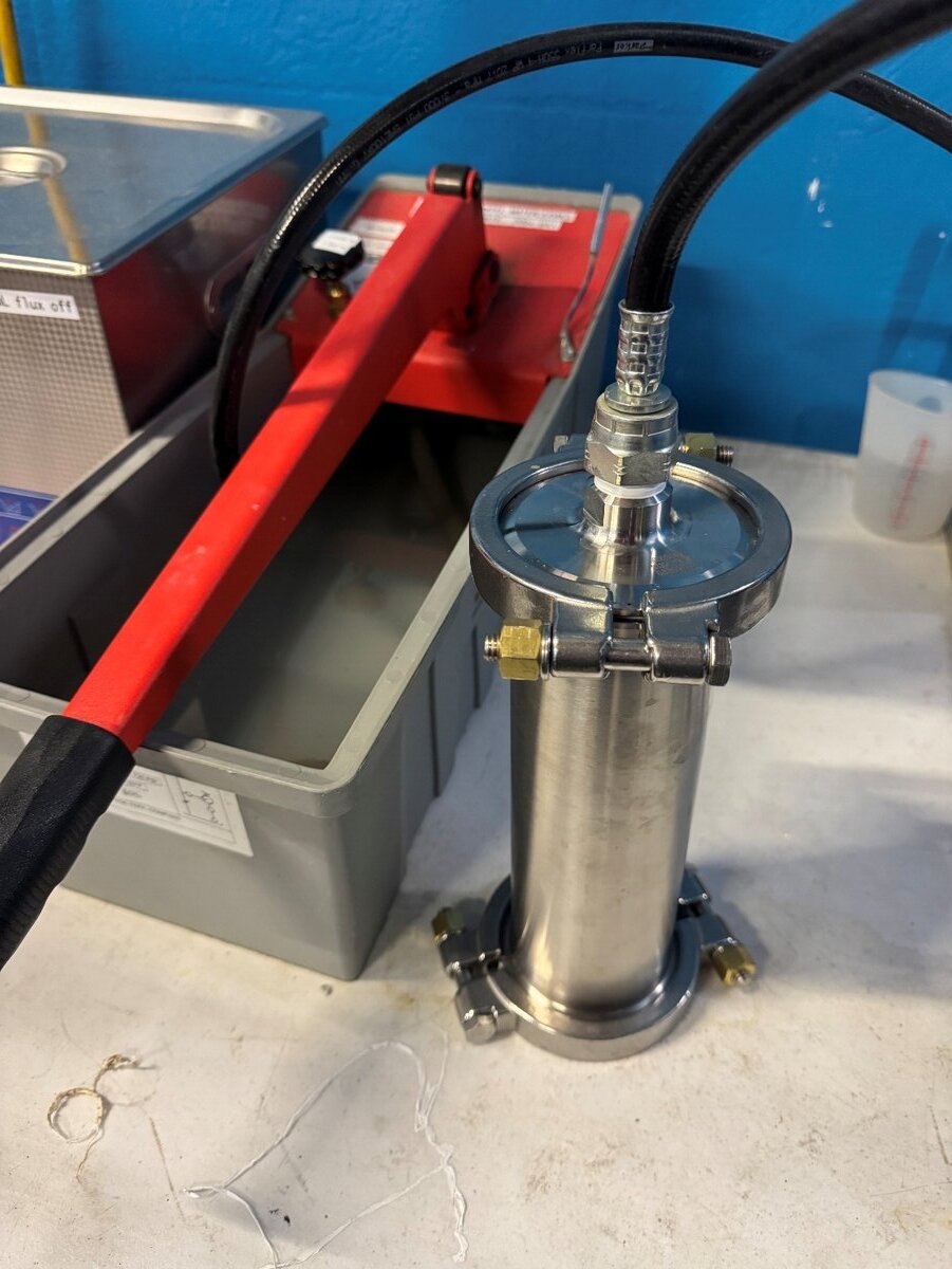
These off-the-shelf parts let you build a small, water-only pressure chamber that connects to a hand hydrostatic test pump:
- Hydrostatic test pump (1/2" NPT outlet) — qty 1
- Shut-off ball valve, 1/2" NPT male × female, 1000 psi (WOG) — qty 1
- Tri-clamp pressure vessel system (3"):
- 3" tri-clamp spool, 9" long — qty 1
- High-pressure clamps, 3" — qty 2
- Solid tri-clamp end cap, 3" — qty 1
- 1/2" MNPT × tri-clamp end cap, 3" — qty 1
- PTFE-envelope tri-clamp gaskets with Viton filler — qty 2
- PTFE thread tape rated for potable water
Safety notes (read first)
- High-pressure systems are dangerous and should be used and assembled carefully.
- Use water only — never air — to pressurize. Using this system with air greatly increases the stored energy.
- Wear eye protection and keep hands clear while pressurizing.
- Use high-pressure-rated tri-clamp hardware and gaskets as listed above. The 3" high-pressure clamps are rated 1000 psi at 70 °F.
- Inspect all seals and clamps before each use; never exceed the hardware rating.
- If pumping takes more than ~10 strokes to start increasing the pressure, there is likely air trapped in the system. Remove the air and try again.
B. Assemble the station (once)
- Thread the shut-off valve's male end into the pump hose outlet, then thread the 1/2" MNPT × tri-clamp end cap into the valve's female end (use pipe tape or paste rated for potable water). The valve now sits between the pump and the chamber.
- Build the vessel: gasket → end cap (with NPT) → clamp → 9" spool → gasket → solid end cap → clamp. Tighten the clamp bolts firmly.
- Fill the spool completely with DI water, then briefly crack the upper joint to burp out any trapped air and re-tighten.
- Connect the pump to the NPT end cap, with the valve open. Keep all wetted parts filled with water during setup.
C. Refill procedure
Before you start
Keep the sensor wet. If a cavitated sensor dries, nanopores foul over time and will not refill properly. Store the probe front in DI water (not tap water) at all times during handling.
1) Flush the system. With the valve open, run DI water through the pump, hose and vessel to push out all air bubbles. Top off the vessel with water.
2) Bag the probes. Place probes in a well-sealed Ziploc® bag filled with DI water. Carefully push out all air so the bag contains only water and the sensor — no bubbles.
3) Load the chamber. Lower the water-filled bag into the vessel already full of water. Overfill slightly so water beads at the rim, then close the top cap and clamp so no air is trapped.
4) Pressurize. With the valve open, slowly pump to ~600 psi (41 bar).
Pressure ceiling. 600 psi is the target and there is no benefit to going higher. Treat 50 bar (725 psi) as a hard ceiling — that is also the maximum rating of the pump specified above. Probes have been taken to 50 bar without damage, so a brief overshoot is not a reason to discard them, but do not work above it.
5) Close the valve and hold. Close the shut-off valve and leave the chamber at pressure for at least 12 hours (overnight is typical). With the valve closed, the chamber holds its own pressure and a bleeding pump check valve cannot drain it.
6) Check that it held, then depressurize. In the morning, open the valve slowly and watch the pump's gauge:
- The gauge jumps back up to near your set pressure → the chamber held, and the refill ran for the full soak.
- The gauge reads zero → the chamber leaked. Re-seat the gaskets, re-tighten the clamps, check for trapped air, and repeat the soak.
Release the remaining pressure slowly, open the chamber, remove the bag, and take out the probes.
7) Keep the probes wet. Immediately cap each probe in a DI-water-filled capsule to keep it hydrated. Fill the capsule ~25% with DI water (leaving room for the probe and a small air pocket), insert the probe gently, then blow the water off the connector so the contacts are dry.
D. Quick post-refill check (recommended)
Before reinstalling, you can do a short bench check:
- Stability in water (15–60 min quick check, or a longer 24 h check if you prefer): in DI water the probe should read near 0 bar (within about ±1 bar) and show a stable voltage without drift.
- (Optional) Brief dry-out response: after fully hydrating, remove from water, gently blot the top surface only, and confirm tension rises promptly; then return it to water before it cavitates.
These checks mirror the lab tests below, so you can verify function before going back to the field.
E. Tips and troubleshooting
- If the probe was allowed to dry, refilling may fail because organic contaminants clog the nanopores. Keeping the sensor wet from removal through refilling gives the best chance of recovery. A probe that cavitated while still installed in the tree is largely protected from airborne contamination, so it is often a good refill candidate.
- Pressure won't hold overnight. With the shut-off valve closed the pump is out of the picture, so a loss of pressure points at the vessel: re-seat the gaskets, re-tighten the clamps, and confirm no air is trapped. Verify the valve itself is fully closed.
- Pressure won't build in the first place. That is the pump, not the chamber — most often trapped air (more than ~10 strokes with no rise), or water weeping past the pump plunger at high pressure.
- After a successful refill, treat the probe as usual in this manual: store it wet, handle it carefully, and re-install it clean.
How to test the sensor in the laboratory
If desired, you may perform two tests for each sensor to verify proper functioning.
Clear the sensing face first. Only run these tests after the mating compound has been cleared from the microchip front. Compound left on the sensing face fouls the nanopores and makes the result meaningless — a stalled dry-out trace then cannot tell you whether the pores are partially blocked or the sensor has cavitated.
This takes a few minutes, not an overnight wait: leave the probe in DI water for a few minutes to soften the dried powder, then rinse gently with a stream of DI water. Never scrub or wipe the face. Residue on the metal body, the tail or the wires does not matter and never needs cleaning.
Test #1: Sensor output is stable in water
- Place the probe sensing head in DI water.
- Connect the sensor to a datalogger and measure its output for 24 hours or longer.
- Look over the data. The sensor should measure close to zero bars, within ±1 bar, for the duration of the test. Small deviations are fine and are usually caused by temperature fluctuations. Likewise the voltage output should be stable, and not vary by more than ±0.2 mV/V. If there are big jumps or drift in the data, the sensor is likely broken.
Test #2: Sensor response in dry air
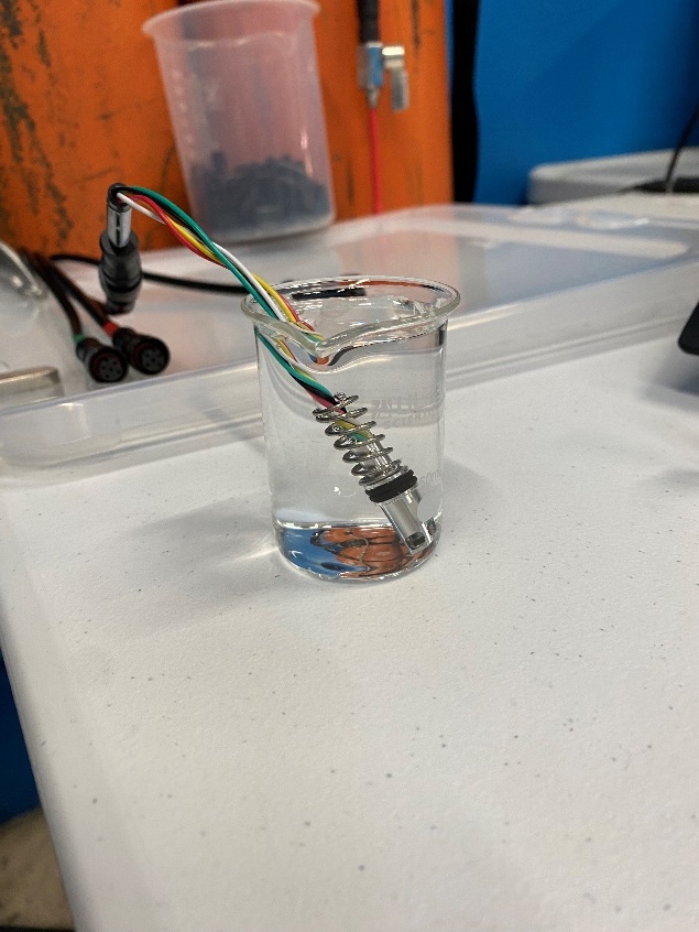 | 1. Place the sensor in a container of DI water for at least an hour to let it relax (fully hydrate) and measure zero pressure. This is the offset voltage (voltage in water). |
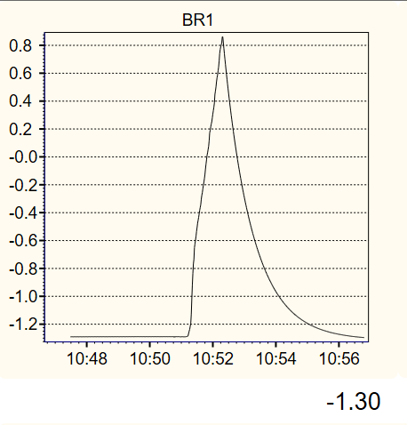 | 2. Measure the sensor's drying-out response to confirm the sensor is full of water (not cavitated). For this test you must have a real-time readout of the sensor that refreshes at least every 5 seconds. The readout can be done by connecting the probe to a scientific logger (e.g. Campbell CR6, CR1000). Easier for SDI-12 sensors: no scientific logger is needed — connect the sensor to the FloraPulse SDI-12 interface box and USB uploader, open app.florapulse.com/calibration-upload in Chrome or Edge, and click Start Response Test. The page reads the sensor once per second, plots it live, guides you through this exact test, and gives a verdict automatically. Starting voltage (probe in water) is approx. -1.3 mV. |
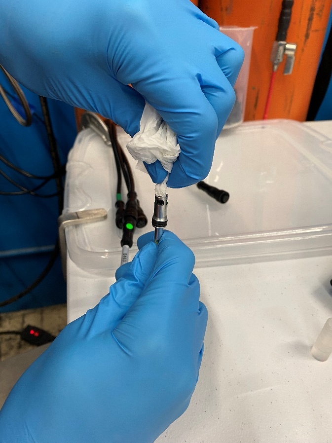 | 3. Pull the sensor out of water and hold it with the chip facing up. Gently use a clean napkin to dry off the top of the chip, being careful not to contaminate it, then watch the sensor output. Wear protective gloves to avoid contaminating the sensor. The sensor will not work if grease or contaminants get on the pores (top of the chip). |
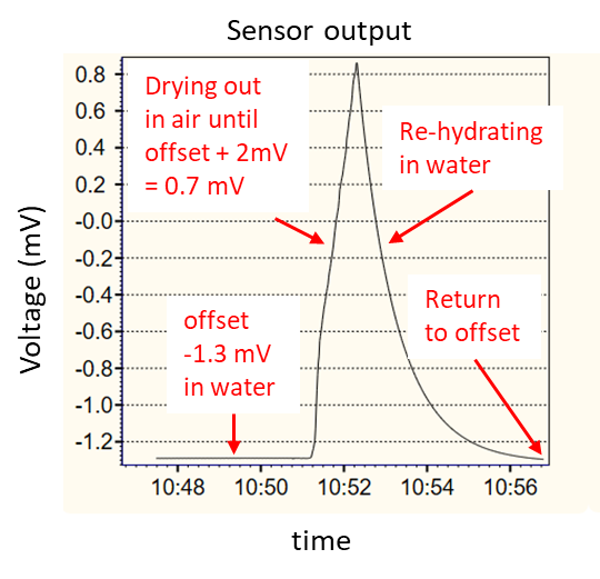 | 4. The sensor output voltage will soon shoot up and start reading increasing tension. Wait until the sensor reads -10 bar (about offset + 2 mV) and then immediately place it back in water. This process should only take a few minutes. It is critical to watch the sensor output carefully, because once the sensor starts drying out it will cavitate within a minute or two if not quickly placed back in water. Ending voltage returned to -1.3 mV after being returned to water. |
Analyze the response test data
The table below shows the 3 stages of the response test (measure offset, dry sensor, re-hydrate sensor), the expected 'good' behavior for each, and potential problems and solutions.
| Stage | Good | Problems | Solutions |
|---|---|---|---|
| Measure offset | Sensor offset should be flat and stable. | Large noise or random jumps. Measured offset slowly decreasing. | The sensor electronics are likely broken. Use a new sensor. The sensor is still not fully re-hydrated. Wait until the line flattens out. |
| Dry sensor to offset+2 mV (-10 bar) | Sensor output shoots up to offset+2 mV in a straight line within ~3 minutes. | Sensor output does not change during dry-out (stays flat). Sensor output increases very slowly and takes 3+ minutes to reach +2 mV. Sensor output increases, then drops sharply back to offset. | Sensor is cavitated or the nanopores are broken. Use a new sensor. Sensor is partially blocked. Re-hydration should also be slow. Try sanding the pores to increase response speed (see below). Sensor cavitated because it dried too much (too much tension), or the pores broke. Use a new sensor. |
| Re-hydrate sensor | Sensor output decreases back towards offset. Voltage goes down by 1 mV within 30 minutes. | Sensor output decreases very slowly, takes 30+ minutes to decrease by 1 mV. Sensor output drops sharply back to offset. | Sensor is partially blocked. Try sanding the pores to increase response speed (see below). Sensor cavitated. Use a new sensor. |
Sand sensor nanopores if needed
Sometimes sensors are slow due to contamination, and it may be possible to remove this contamination by lightly sanding the pore surface. This process should only be done carefully and only when necessary, because excessive sanding will eventually break the sensor.
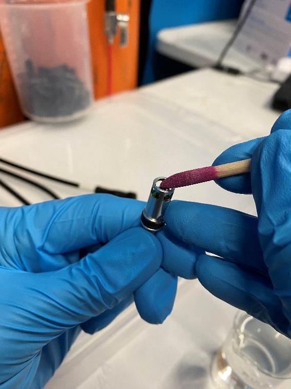 | Sand the chip surface. Pull the sensor out of water and leave the pore surface wet to prevent dry-out and cavitation. Using a clean sanding stick, apply light pressure and abrade the chip top surface back and forth for 60 seconds, at a rate of 2 strokes per second. You should hear a scratching noise as the sanding stick abrades the nanopores to open them up. It may be necessary to rotate the sanding stick as the abrasive wears out, to use fresh abrasive. |
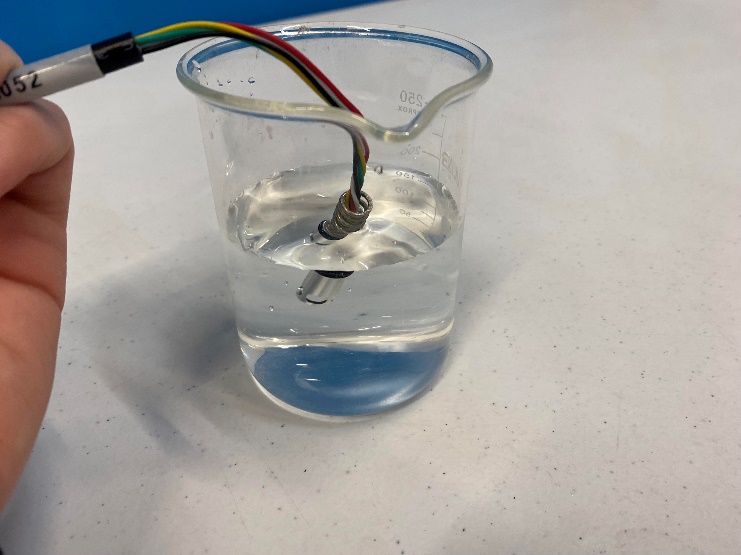 | Rinse the sanding debris. Place the sensor back in DI water and swish it around to rinse off sanding debris. |
Let the sensor rest for 30+ minutes in DI water to fully re-hydrate, then re-test for response speed as explained above (Test #2).
You may repeat sanding one more time if response speed is still slow. Further sanding will not help and will eventually destroy the sensor.
Slow sensors will still measure water potential, but their response will lag the tree water potential, so accuracy will be impacted.
Sensor re-install
To reuse the sensor, you will need to gather the following materials:
- Fresh mating compound. The mating syringe may dry out after sitting around for a long time. You can re-hydrate it by adding a couple of drops of water at a time and mixing until a 'syrup' consistency. Add liquid very slowly, because the mating compound will easily become too runny (and then you will have to wait for it to dry out).
- New sleeve. The sleeve nails always break when removed — you will need to use a new sleeve. The cap can be re-used.
- The rest of the materials from your install kit can be re-used.
See the installation manual for the full list of install tools and installation instructions.